00900068-02_SM_ASM_ProcessLens_EN.pdf - 第42页
ASM Proces sLens Single - l ane 03/2020 Edit ion 42 3.14.1 Check the functi on of the conv eyor motor Requirem ents: ● Machine is switche d on . ● Circuit boar d is p laced at t he be ginning of the m achine . Figure 3- …

ASM ProcessLens Single-lane 03/2020 Edition
41
Key:
1) Screw (4 x)
2) Gear
3) Conveyor motor belt
Figure 3-43: Conveyor motor (from back)
2. Unscrew the screws (4 x) using an Allen Key size 4.0.
3. Take off the conveyor motor belt.
4. Take out the motor of the machine
Key:
1) Conveyor motor
2) Gear
3) Screw
Figure 3-44: Conveyor motor
5. Unscrew the screw off the gear of the old motor and replace it onto the new motor using an
Allen Key size 4.0.
6. Put the motor back in place.
7. Put the belt on and tighten the screws.
8. Connect the connectors to the TSP400.
Installation
Follow the removal instructions in reverse order for installation.
ASM ProcessLens Single-lane 03/2020 Edition
42
3.14.1 Check the function of the conveyor motor
Requirements:
● Machine is switched on.
● Circuit board is placed at the beginning of the machine.
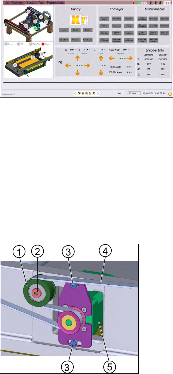
Figure 3-45: Diagnostic page
1. Go to the diagnostic page.
2. Click on the tab "Unit function".
3. Go to the section "Conveyor".
4. Click the button "PCB In" and the button "PCB Out".
5. If the circuit board cannot move through the machine the conveyor system needs to be
adjusted.
3.15 Changing the width adjustment belt
Requirements:
● Machine is switched off.
● Tension meter.
Key:
1) Tension ring
2) Screw A
3) Screw B (2 x)
4) Belt
5) Motor
Figure 3-46; Motor for the width adjustment
ASM ProcessLens Single-lane 03/2020 Edition
43
1. Loosen the tension ring by loosen the screw A (2).
2. Remove the motor by loosen the screws B (3) using an Allen key size 3.
3. Remove the belt (4) and replace it with a new one.
3.15.1 Assembling of the width adjustment belt
Requirements:
● Machine is switched off.
● Tension meter.
● Tension ring is loosened.
● Inspection circuit boards (2 x).
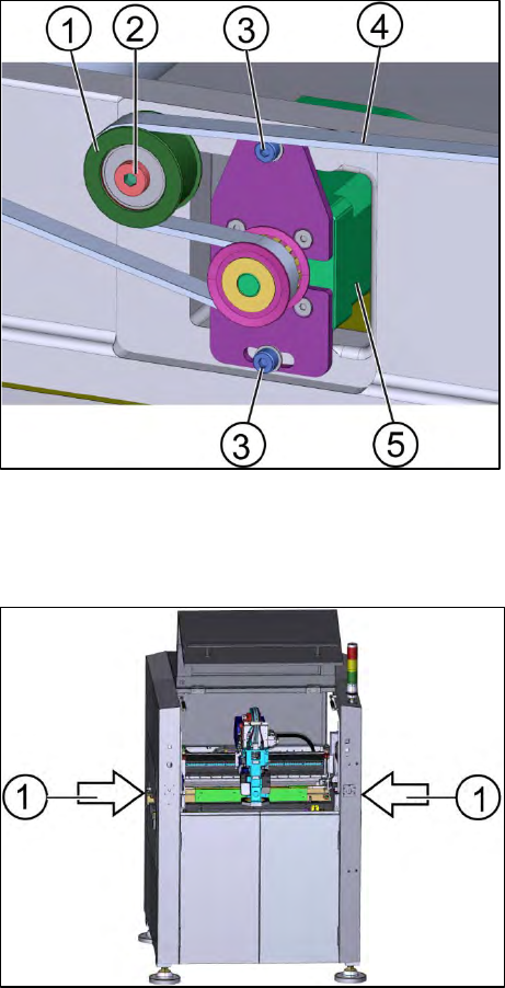
Key:
1) Tension ring
2) Screw A
3) Screw B (2 x)
4) Width adjustment belt
5) Motor
Figure 3-47: Motor of the width adjustment
1. Put the width adjustment belt (4) in position.
2. Place the two inspection circuit boards between the two conveyor systems.
Figure 3-48: Machine
Key:
1) Position of the inspection circuit boards