00900068-02_SM_ASM_ProcessLens_EN.pdf - 第44页
ASM Proces sLens Single - l ane 03/2020 Edit ion 44 NOTICE A lignment of the conveyor units T he distanc e bet ween the two con veyor u nits nee d to allo w the inspec tion c ircuit boar ds to pass thro ugh with ease. Fo…
ASM ProcessLens Single-lane 03/2020 Edition
43
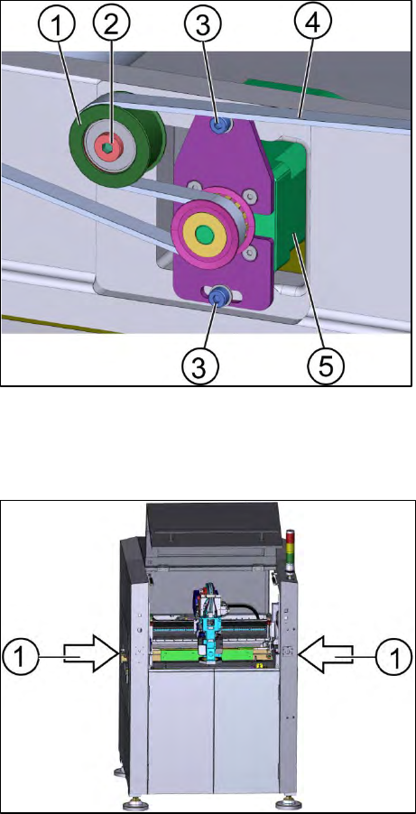
1. Loosen the tension ring by loosen the screw A (2).
2. Remove the motor by loosen the screws B (3) using an Allen key size 3.
3. Remove the belt (4) and replace it with a new one.
3.15.1 Assembling of the width adjustment belt
Requirements:
● Machine is switched off.
● Tension meter.
● Tension ring is loosened.
● Inspection circuit boards (2 x).
Key:
1) Tension ring
2) Screw A
3) Screw B (2 x)
4) Width adjustment belt
5) Motor
Figure 3-47: Motor of the width adjustment
1. Put the width adjustment belt (4) in position.
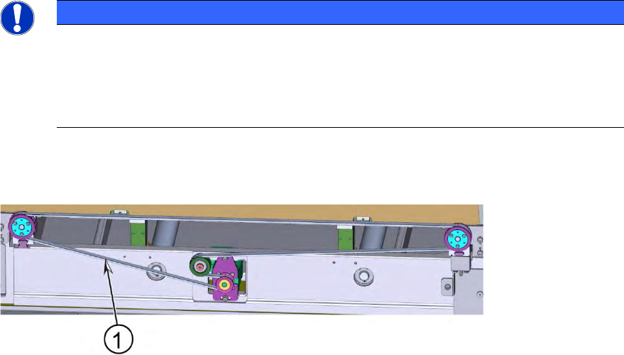
2. Place the two inspection circuit boards between the two conveyor systems.
Figure 3-48: Machine
Key:
1) Position of the inspection circuit boards
ASM ProcessLens Single-lane 03/2020 Edition
44
NOTICE
Alignment of the conveyor units
The distance between the two conveyor units need to allow the inspection circuit boards
to pass through with ease. For that the width of the conveyor units need to be parallel to
each other. The inspection circuit boards help to achieve the alignment of the conveyor
units.
3. Fasten the tension ring (1).
4. Check whether the boards can move through the conveyer systems with ease. If not adjust the
width adjustment belt.
Key:
1) Measurement
point for the
tension
Figure 3-49: Width adjustment belt
5. Check the tension of the width adjustment belt at the measurement point using a tension meter.
6. The tension should be 60 +/- 6 Hz.
3.15.2 Adjusting the width adjustment belt
Requirements:
● Machine is switched off.
● Tension ring is loosened.
● Inspection board (2 x).
1. Find out which end of the conveyor unit needs to be adjusted.
2. Fixate the gear and slide the width adjustment belt further over the gear so that the width
adjustment belt is one position further ahead or reverse.
3. Continue until the conveyor units are parallel to each other and the inspections boards move
through the conveyor units with ease.
4. When the width adjustment belt is in the right position the tension must be fastened again.
5. Go to section 3.15.3 Check system test to check the function.
3.15.3 Check system test
Requirement:
● Machine is switched on.
ASM ProcessLens Single-lane 03/2020 Edition
45
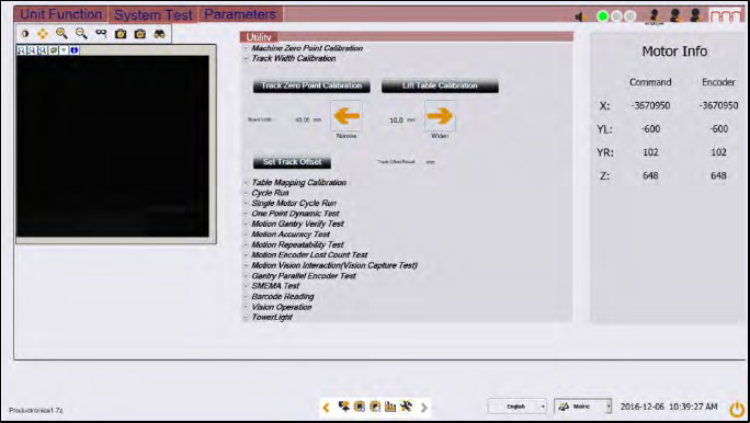
Figure 3-50: Diagnostic page
1. Open the Diagnostic page.
2. Go to the tab "System Test"
3. Click on the button "Track zero point calibration"
4. A message will indicate that the calibration was successful.
5. Go to the tab Unit function.
6. Proceed to the conveyer section and press the buttons "Lift Home", "Lift up" and "Lift down" to
check the function of the lifting table.
7. On screen messages will confirm the successful function test of the lifting table.
8. If the conveyor system does not move or any fault message occurs, the conveyor system
needs to be adjusted.