00900068-02_SM_ASM_ProcessLens_EN.pdf - 第51页
ASM Proces sLens Single - l ane 03/2020 Edit ion 51 3.18 Changing the spar e parts of the stopper and s ensor s rail The st opper and sens ors ra il cons ists of these fol lowing s pare par ts: ● Input sens or ● Sonar se…
ASM ProcessLens Single-lane 03/2020 Edition
50
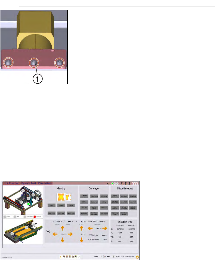
must hit the stopper screw.
Key:
1) Screw (3 x)
Figure 3-58: Lifting table motor
4. Fasten the screws (1) of the conveyor motor using an Allen key size 5.0.
5. Put the lifting table plate back on.
6. Fasten the four screws of the lifting table plate using an Allen key size 5.
7. Check the function of the table go to section 3.17.2 Check the function of the motor of the lifting
table.
3.17.2 Check the function of the motor of the lifting table
Requirement:
● Machine is switched on.
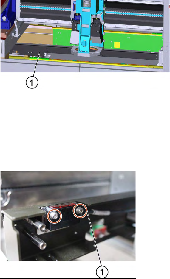
Figure 3-59: Diagnostic page
1. Go to the diagnostic pages.
2. Click on the tab "Unit Function".
3. Click on the buttons "Lift Home", "Lift Up" and "Lift Down".
4. If the conveyor system does not move or any fault messages occur see troubleshooting.
ASM ProcessLens Single-lane 03/2020 Edition
51
3.18 Changing the spare parts of the stopper and sensors rail
The stopper and sensors rail consists of these following spare parts:
● Input sensor
● Sonar sensor
● Stopper
● Output sensor
3.18.1 Changing the sensors of the stopper and sensors rail
Key:
1) Stopper and sensors rail
Figure 3-60: Stopper unit
Requirement:
● Machine is switched off.
1. Remove the cover of the stopper and sensors rail by unscrewing 10 x screws using an Allen
key size 2.0 (small screws).
2. Furthermore unscrew 4 x screws using an Allen key size 2.5 (large screws).
3. The cover is removed.
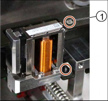
Key:
1) Screw (2 x)
Figure 3-61: Sensor
4. Unscrew the screws to remove the input sensor, sonar sensor or output senor using an Allen
key size 2.0.
5. Change the sensors and tighten the screws (2 x).
6. Put the cover back onto the stopper and sensors rail and tighten the screws (14 x).
ASM ProcessLens Single-lane 03/2020 Edition
52
Installation
Follow the removal instructions in reverse order for installation.
3.18.2 Changing the stopper of the stopper and sensors rail
Key:
1) Screw (2 x)
Figure 3-62: Stopper
Requirement:
● Machine is switched off.
1. Remove the cover of the stopper and sensors rail by unscrewing 10 x screws using an Allen
key size 2.0 (small screws).
2. Furthermore unscrew 4 x screws using an Allen key size 2.5 (large screws).
3. The cover is removed.
4. Remove the stopper by unscrewing the screws (2 x) using an Allen key size 2.0.
5. Put the stopper back in place and tighten the screws (2 x).
6. Put the cover back onto the stopper unit and tighten the screws (14 x).
Installation
Follow the removal instructions in reverse order for installation.