00900068-02_SM_ASM_ProcessLens_EN.pdf - 第52页
ASM Proces sLens Single - l ane 03/2020 Edit ion 52 Installation Follow th e rem oval instruct ions in rever se order f or install ation. 3.18.2 Changing the stopper of the stoppe r and sensors rail Ke y: 1) Screw (2 x) …
ASM ProcessLens Single-lane 03/2020 Edition
51
3.18 Changing the spare parts of the stopper and sensors rail
The stopper and sensors rail consists of these following spare parts:
● Input sensor
● Sonar sensor
● Stopper
● Output sensor
3.18.1 Changing the sensors of the stopper and sensors rail
Key:
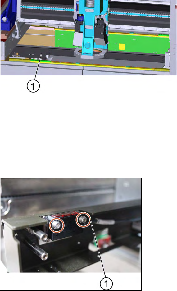
1) Stopper and sensors rail
Figure 3-60: Stopper unit
Requirement:
● Machine is switched off.
1. Remove the cover of the stopper and sensors rail by unscrewing 10 x screws using an Allen
key size 2.0 (small screws).
2. Furthermore unscrew 4 x screws using an Allen key size 2.5 (large screws).
3. The cover is removed.
Key:
1) Screw (2 x)
Figure 3-61: Sensor
4. Unscrew the screws to remove the input sensor, sonar sensor or output senor using an Allen
key size 2.0.
5. Change the sensors and tighten the screws (2 x).
6. Put the cover back onto the stopper and sensors rail and tighten the screws (14 x).
ASM ProcessLens Single-lane 03/2020 Edition
52
Installation
Follow the removal instructions in reverse order for installation.
3.18.2 Changing the stopper of the stopper and sensors rail
Key:
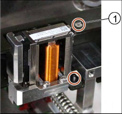
1) Screw (2 x)
Figure 3-62: Stopper
Requirement:
● Machine is switched off.
1. Remove the cover of the stopper and sensors rail by unscrewing 10 x screws using an Allen
key size 2.0 (small screws).
2. Furthermore unscrew 4 x screws using an Allen key size 2.5 (large screws).
3. The cover is removed.
4. Remove the stopper by unscrewing the screws (2 x) using an Allen key size 2.0.
5. Put the stopper back in place and tighten the screws (2 x).
6. Put the cover back onto the stopper unit and tighten the screws (14 x).
Installation
Follow the removal instructions in reverse order for installation.
ASM ProcessLens Single-lane 03/2020 Edition
53
3.19 Changing the TSP400
3.19.1 Removing the TSP400
Key:
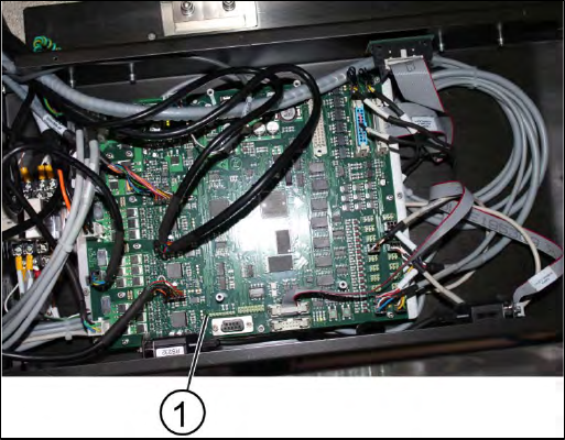
1) TSP400
Figure 3-63: TSP400
Requirement:
● Machine is switched off.
1. Disconnect all connectors of the board.
2. Unscrew all screws (16) using an T shaped Allen key size 2.5.
3. Remove the circuit board.
3.19.2 Replacing the TSP400
Requirement:
● Machine is shut off.
● TSP400 is dismantled.
1. Place the new TSP400 into the box.
2. Tighten the screws (16 x).