00900068-02_SM_ASM_ProcessLens_EN.pdf - 第70页
ASM Proces sLens Single - l ane 03/2020 Edit ion 70 4.4 Cali brations - Table Mappi ng NOTICE Note Mappin g pr ocedures for C onve yor with op tion Left - Rig ht or Right - Left has the sa m e procedures . ● Left - Right…
ASM ProcessLens Single-lane 03/2020 Edition
69
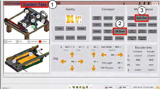
Step 8
1.
Click on System Test.
2.
Click Lift Down.
3.
Click Open Door.
4.
Disconnect the lighting cable and
remove the target.
ASM ProcessLens Single-lane 03/2020 Edition
70
4.4 Calibrations - Table Mapping
NOTICE
Note
Mapping procedures for Conveyor with option Left-Right or Right-Left has the same
procedures.
● Left-Right Transport - input mapping plate from left
● Right-Left Transport - input mapping plate from right
Preparation
This procedure compares the positions of the camera across the table (work area) against a target
glass plate mapped at a higher level of accuracy and compensates for the positional differences.
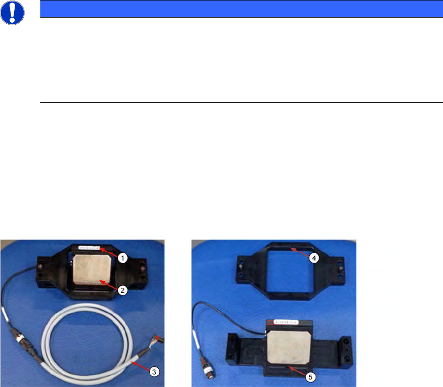
1. Prepare the coaxial light assembly. The Coaxial light consists of a cable (3), a bracket (4) and
a lighting assembly (5). The glass surfaces are protected by 2 clip-on covers.
2. Remove the 2 clip-on metal protective covers (2).
3. Clean the glass surfaces of the lighting assembly if necessary with a lint free cloth.
1. The ProcessLens uses the SIPLACE SX-Series mapping plate version 5 (1). Each Mapping
glass plate has its own unique positional data map saved in a CD or in a Flash drive.
The data is in stored in a file named mp_mess.dat.
2. Open the mp_mess.dat file in the mapping CD or flash drive that comes with the mapping
plate. Compare the plate reference number (2) against the number labeled on the plate.
They should be the same.
ASM ProcessLens Single-lane 03/2020 Edition
71
4.4.1 Table Mapping: Teach
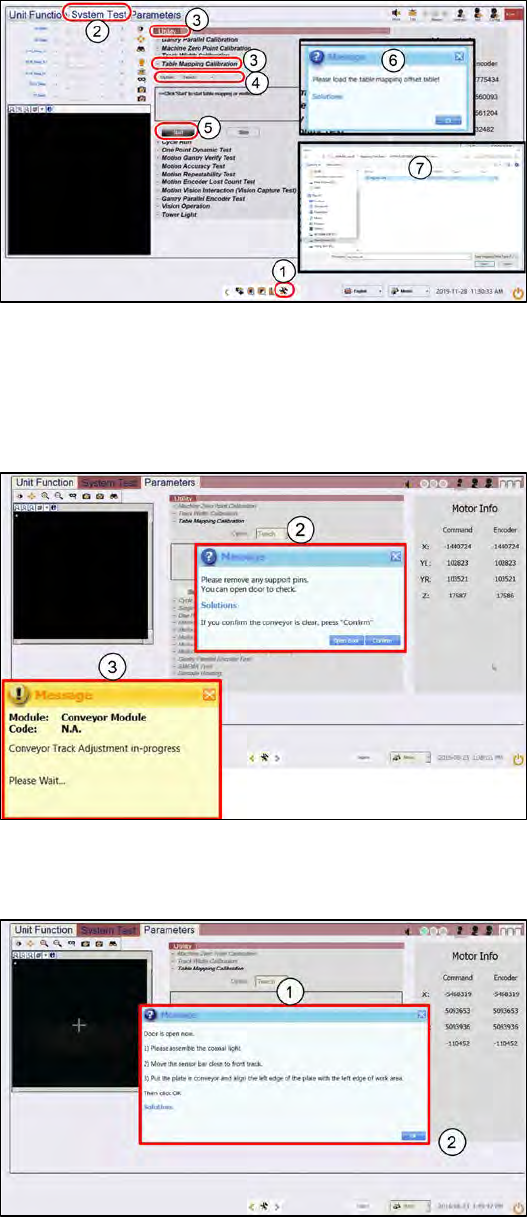
Step 1
1.
Go to the DiagnosticPage
2.
Click System Test.
3.
Go to Utility, Table Mapping
Calibration
4.
Under Option, select Teach.
5.
Click Start.
6.
A message asking for the
mapping data file pops up.
7.
Copy the "mp_mess.dat" file to
the "c:\system\AS Table
Map Offset\" folder.
Switch back to ProcessLens GUI,
click Yes.
Step 2
1.
Open the cover and remove any
support pins from the table.
2.
Close the cover then click
Confirm to continue.
3.
Wait while the conveyor adjust to
a width of 560mm.
Step 3
1.
A message pops up after the
conveyor width reaches 560mm.
Open the machine cover.