00900068-02_SM_ASM_ProcessLens_EN.pdf - 第72页
ASM Proces sLens Single - l ane 03/2020 Edit ion 72 Step 4 Install th e Coaxia l Light as sem bl y onto th e cam era modul e as sho wn bel ow. 1. Place the brack et over the camer a ring fram e. 2. Attach the coax ial li…
ASM ProcessLens Single-lane 03/2020 Edition
71
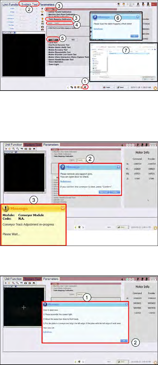
4.4.1 Table Mapping: Teach
Step 1
1.
Go to the DiagnosticPage
2.
Click System Test.
3.
Go to Utility, Table Mapping
Calibration
4.
Under Option, select Teach.
5.
Click Start.
6.
A message asking for the
mapping data file pops up.
7.
Copy the "mp_mess.dat" file to
the "c:\system\AS Table
Map Offset\" folder.
Switch back to ProcessLens GUI,
click Yes.
Step 2
1.
Open the cover and remove any
support pins from the table.
2.
Close the cover then click
Confirm to continue.
3.
Wait while the conveyor adjust to
a width of 560mm.
Step 3
1.
A message pops up after the
conveyor width reaches 560mm.
Open the machine cover.
ASM ProcessLens Single-lane 03/2020 Edition
72
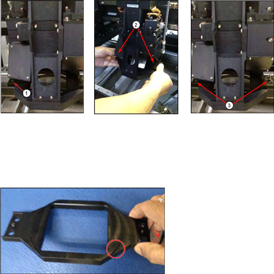
Step 4
Install the Coaxial Light assembly onto the camera module as shown below.
1. Place the bracket over the
camera ring frame.
2. Attach the coaxial lighting
assembly from below the
camera ring frame to the
bracket above the ring
frame with the 2 screws.
The camera ring frame is
sandwiched by this
assembly.
3. Tighten the 2 screws.
The coaxial light assembly
should be secured to the
camera ring light frame with
no movement.
4. The circular protrusion at the
bottom side of the bracket should
sit face down snugly inside the
ling light assembly.
ASM ProcessLens Single-lane 03/2020 Edition
73
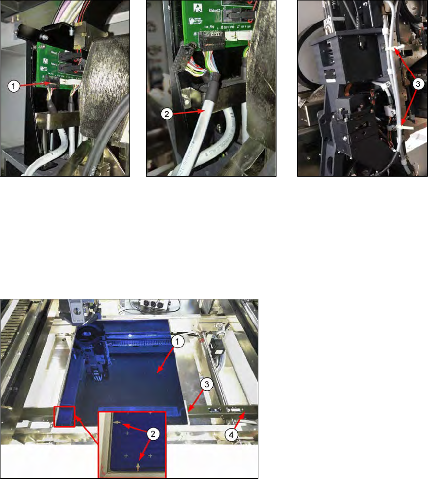
Step 5
Move the camera head module to the left for easy access.
1. Gently pull out low ring light
connector by holding onto
the connector´s body. Do
not pull using the wires.
Use a flat fead screwdrive
to pry if necessary.
2. Plug-in the coaxial light
cable.
3. Secure the coaxial light
cable with cable ties to
prevent flapping when the
cameras move.
Step 6
1.
Put in the mapping plate.
2.
Refer to bottom left hand corner
of the plate. The arrows on the
long side is pointing towards the
left and the arrows on the short
side of the plate is pointing
towards the front.
3.
Leading edge.
4.
Pull the sensor bar to the front
and position under the leading
aluminium edge of the plate.