00900068-02_SM_ASM_ProcessLens_EN.pdf - 第88页
ASM Proces sLens Single - l ane 03/2020 Edit ion 88 1. Examine each of the 5 meas urement varia bles. 2. Check that al l the %GR &R ar e less tha n 10%. e.g. Volum e(% ) repeatabi lity for all the dif ferent or ienta…
ASM ProcessLens Single-lane 03/2020 Edition
87
1.
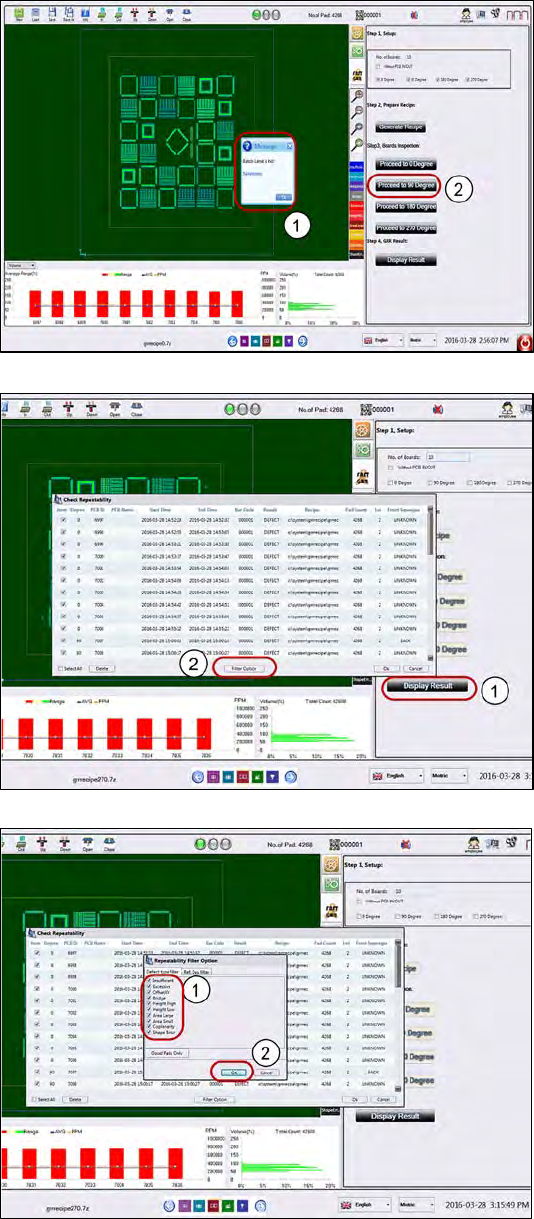
At the end of 10 replicate
measurements, the "Batch
limit hit" message box will
pop up. Click Ok.
2.
Remove and rotate the board to
90° and place it on the input
section Click Proceed to 90
Degree to run the GR&R
inspection at 90° orientation.
1.
Upon completing the last
measurement, click Display
Result.
2.
Click on Filter option to choose
the pads for calculation.
1.
Tick all the defect type check
boxes.
2.
Click Ok to all message boxes to
generate the Repeatability
Report.
ASM ProcessLens Single-lane 03/2020 Edition
88
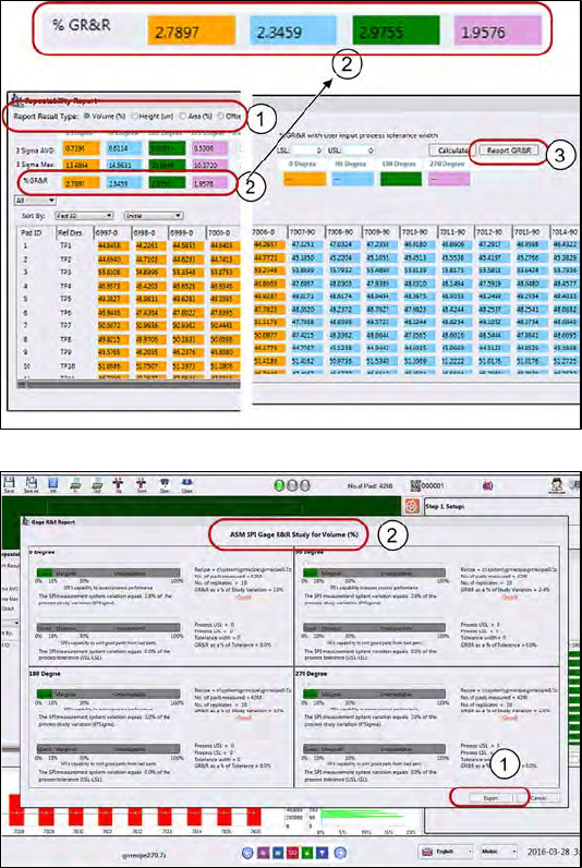
1.
Examine each of the 5
measurement variables.
2.
Check that all the %GR&R are
less than 10%.
e.g. Volume(%) repeatability for
all the different orientations are
less than 10% which is good.
3.
Click Report GR&R to produce a
report.
1.
Click Export to export the GR&R
results for the variable selected.
Repeat for all measured
variables.
Keep the report as proof of GR&R
capability.
What to do if the GR&R fails?
● Measure again: fiber, dust could have fallen on the pad during GR&R test.
● Is the machine cover opened? Is the board properly clamped?
● Is the board bouncing because it´s thin, not properly supported?
● Is the paste on the board slumping?▪Check for hardware issues.
● Was there any disturbance to the CR&R process to the target?
ASM ProcessLens Single-lane 03/2020 Edition
89
Figure 2-1: Machine overview .......................................................................................................... 15
Figure 2-2: Machine overview .......................................................................................................... 15
Figure 3-1: Optical head ................................................................................................................... 17
Figure 3-2: Cover for cables ............................................................................................................. 17
Figure 3-3:Cable clamp .................................................................................................................... 18
Figure 3-4: Optical head ................................................................................................................... 18
Figure 3-5: Optical head ................................................................................................................... 19
Figure 3-6: Low Ringlight assembly ................................................................................................. 20
Figure 3-7: Connectors at low Ringlight assembly ........................................................................... 20
Figure 3-8: Low Ringlight assembly ................................................................................................. 21
Figure 3-9: Low Ringlight assembly ................................................................................................. 22
Figure 3-10: Low Ringlight assembly (dismantled) .......................................................................... 22
Figure 3-11: High Ringlight assembly (from below) ......................................................................... 23
Figure 3-12: High Ringlight assembly (dismantled) ......................................................................... 24
Figure 3-13: High Ringlight assembly (dismantled) ......................................................................... 24
Figure 3-14: Diagnostic page ........................................................................................................... 25
Figure 3-15: Lighting control page ................................................................................................... 25
Figure 3-16: DLP modules ............................................................................................................... 26
Figure 3-17: Cover for DLP module ................................................................................................. 26
Figure 3-18: Cover for DMD module ................................................................................................ 27
Figure 3-19: DMD module ................................................................................................................ 27
Figure 3-20: DLP module ................................................................................................................. 28
Figure 3-21: Connector of DLP module ........................................................................................... 28
Figure 3-22: DLP Controller Software .............................................................................................. 29
Figure 3-23: DLP Upgrade Tool ....................................................................................................... 30
Figure 3-24: DLP Upgrade Tool ....................................................................................................... 30
Figure 3-25: Reader ......................................................................................................................... 31
Figure 3-26: Encoder........................................................................................................................ 31
Figure 3-27: Spacer.......................................................................................................................... 31
Figure 3-28: Position of spacer ........................................................................................................ 32
Figure 3-29: Position of the flexures and the optical head ............................................................... 33
Figure 3-30: Flexures ....................................................................................................................... 33
Figure 3-31: Gantry Index ParallelTool ............................................................................................ 34
Figure 3-32: Diagnostic page ........................................................................................................... 35
Figure 3-33: Y scale bar ................................................................................................................... 35
Figure 3-34: Y scale bar ................................................................................................................... 36
Figure 3-35: Gear and conveyor rod ................................................................................................ 37
Figure 3-36: Clamping plate ............................................................................................................. 37
Figure 3-37: Tension ring of the conveyor unit ................................................................................ 38
Figure 3-38: Gear ............................................................................................................................. 38
Figure 3-39: Conveyor belt ............................................................................................................... 39
Figure 3-40: Diagnostic page ........................................................................................................... 39
Figure 3-41: Overview of the conveyor motor .................................................................................. 40
Figure 3-42: TSP400 ........................................................................................................................ 40
Figure 3-43: Conveyor motor (from back) ........................................................................................ 41
Figure 3-44: Conveyor motor ........................................................................................................... 41
Figure 3-45: Diagnostic page ........................................................................................................... 42
Figure 3-46; Motor for the width adjustment .................................................................................... 42
Figure 3-47: Motor of the width adjustment ..................................................................................... 43
Figure 3-48: Machine ....................................................................................................................... 43
Figure 3-49: Width adjustment belt .................................................................................................. 44
Figure 3-50: Diagnostic page ........................................................................................................... 45
Figure 3-51: Motor of the width adjustment ..................................................................................... 46
Figure 3-52: TSP400 ........................................................................................................................ 46
Figure 3-53: Diagnostic page ........................................................................................................... 47
Figure 3-54: Lifting plate .................................................................................................................. 48
Figure 3-55: Lifting table motor ........................................................................................................ 48
Figure 3-56: Lifting table motor ........................................................................................................ 49
Figure 3-57: Lifting table motor ........................................................................................................ 49
Figure 3-58: Lifting table motor ........................................................................................................ 50
Figure 3-59: Diagnostic page ........................................................................................................... 50