00900068-02_SM_ASM_ProcessLens_EN.pdf - 第89页
ASM Proces sLens Single - l ane 03/2020 Edit ion 89 Figure 2 - 1: Machi ne overvi ew .......................................................................................................... 15 Figure 2 - 2: Machi ne ov…
ASM ProcessLens Single-lane 03/2020 Edition
88
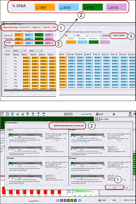
1.
Examine each of the 5
measurement variables.
2.
Check that all the %GR&R are
less than 10%.
e.g. Volume(%) repeatability for
all the different orientations are
less than 10% which is good.
3.
Click Report GR&R to produce a
report.
1.
Click Export to export the GR&R
results for the variable selected.
Repeat for all measured
variables.
Keep the report as proof of GR&R
capability.
What to do if the GR&R fails?
● Measure again: fiber, dust could have fallen on the pad during GR&R test.
● Is the machine cover opened? Is the board properly clamped?
● Is the board bouncing because it´s thin, not properly supported?
● Is the paste on the board slumping?▪Check for hardware issues.
● Was there any disturbance to the CR&R process to the target?
ASM ProcessLens Single-lane 03/2020 Edition
89
Figure 2-1: Machine overview .......................................................................................................... 15
Figure 2-2: Machine overview .......................................................................................................... 15
Figure 3-1: Optical head ................................................................................................................... 17
Figure 3-2: Cover for cables ............................................................................................................. 17
Figure 3-3:Cable clamp .................................................................................................................... 18
Figure 3-4: Optical head ................................................................................................................... 18
Figure 3-5: Optical head ................................................................................................................... 19
Figure 3-6: Low Ringlight assembly ................................................................................................. 20
Figure 3-7: Connectors at low Ringlight assembly ........................................................................... 20
Figure 3-8: Low Ringlight assembly ................................................................................................. 21
Figure 3-9: Low Ringlight assembly ................................................................................................. 22
Figure 3-10: Low Ringlight assembly (dismantled) .......................................................................... 22
Figure 3-11: High Ringlight assembly (from below) ......................................................................... 23
Figure 3-12: High Ringlight assembly (dismantled) ......................................................................... 24
Figure 3-13: High Ringlight assembly (dismantled) ......................................................................... 24
Figure 3-14: Diagnostic page ........................................................................................................... 25
Figure 3-15: Lighting control page ................................................................................................... 25
Figure 3-16: DLP modules ............................................................................................................... 26
Figure 3-17: Cover for DLP module ................................................................................................. 26
Figure 3-18: Cover for DMD module ................................................................................................ 27
Figure 3-19: DMD module ................................................................................................................ 27
Figure 3-20: DLP module ................................................................................................................. 28
Figure 3-21: Connector of DLP module ........................................................................................... 28
Figure 3-22: DLP Controller Software .............................................................................................. 29
Figure 3-23: DLP Upgrade Tool ....................................................................................................... 30
Figure 3-24: DLP Upgrade Tool ....................................................................................................... 30
Figure 3-25: Reader ......................................................................................................................... 31
Figure 3-26: Encoder........................................................................................................................ 31
Figure 3-27: Spacer.......................................................................................................................... 31
Figure 3-28: Position of spacer ........................................................................................................ 32
Figure 3-29: Position of the flexures and the optical head ............................................................... 33
Figure 3-30: Flexures ....................................................................................................................... 33
Figure 3-31: Gantry Index ParallelTool ............................................................................................ 34
Figure 3-32: Diagnostic page ........................................................................................................... 35
Figure 3-33: Y scale bar ................................................................................................................... 35
Figure 3-34: Y scale bar ................................................................................................................... 36
Figure 3-35: Gear and conveyor rod ................................................................................................ 37
Figure 3-36: Clamping plate ............................................................................................................. 37
Figure 3-37: Tension ring of the conveyor unit ................................................................................ 38
Figure 3-38: Gear ............................................................................................................................. 38
Figure 3-39: Conveyor belt ............................................................................................................... 39
Figure 3-40: Diagnostic page ........................................................................................................... 39
Figure 3-41: Overview of the conveyor motor .................................................................................. 40
Figure 3-42: TSP400 ........................................................................................................................ 40
Figure 3-43: Conveyor motor (from back) ........................................................................................ 41
Figure 3-44: Conveyor motor ........................................................................................................... 41
Figure 3-45: Diagnostic page ........................................................................................................... 42
Figure 3-46; Motor for the width adjustment .................................................................................... 42
Figure 3-47: Motor of the width adjustment ..................................................................................... 43
Figure 3-48: Machine ....................................................................................................................... 43
Figure 3-49: Width adjustment belt .................................................................................................. 44
Figure 3-50: Diagnostic page ........................................................................................................... 45
Figure 3-51: Motor of the width adjustment ..................................................................................... 46
Figure 3-52: TSP400 ........................................................................................................................ 46
Figure 3-53: Diagnostic page ........................................................................................................... 47
Figure 3-54: Lifting plate .................................................................................................................. 48
Figure 3-55: Lifting table motor ........................................................................................................ 48
Figure 3-56: Lifting table motor ........................................................................................................ 49
Figure 3-57: Lifting table motor ........................................................................................................ 49
Figure 3-58: Lifting table motor ........................................................................................................ 50
Figure 3-59: Diagnostic page ........................................................................................................... 50
ASM ProcessLens Single-lane 03/2020 Edition
90
Figure 3-60: Stopper unit ................................................................................................................. 51
Figure 3-61: Sensor.......................................................................................................................... 51
Figure 3-62: Stopper ........................................................................................................................ 52
Figure 3-63: TSP400 ........................................................................................................................ 53
Figure 3-64: Switch at TSP400 ........................................................................................................ 54
Figure 3-65: Jumpers at TSP400 ..................................................................................................... 54
Figure 3-66: TSP400 version number .............................................................................................. 55