00193502-01.pdf - 第24页
Retrofit instructions Short Sleeve 05/2004 Edition 24 4 Optimisation process Comp. higher than 8.5mm ? STOP Optimisation process Rest riction s fulfilled? YES NO Step 1 : Bin d t he high c omp one nt t o la s t ma ch in …
Retrofit instructions Short Sleeve
05/2004 Edition
23
4.2 Line Computer Modifications
4.2.1 Changing in the GF Editor
To make a scheduling of the 10.7mm high component possible, the maximum height of the com-
ponent has to be changed to 8.5mm in the editor. The last 2.2mm are added to the tolerances.
E.g. a component with 10.7mm height: type 8.5mm in the standard windows for the component
height and the remaining 2.2mm add to the tolerances. 4
All further component related values stay in the same way and are not modified. 4
Program as a nozzle the special nozzle beginning with number 990 or 790! The sensor type stay
as usual number 12 or 13. 4
Please consider the component size related restrictions at the 12 or 6 star head. 4
12 Segment revolver head max. component size:10mm
6 Segment revolver head max. component size:30mm 4
4.2.2 Optimisation dialog
Due to the modified component height in the GF editor, during the optimisation process the ope-
rator has to take care on following issues: 4
You cannot start a usual optimisation as known from the LCU process. 4
When a component with 10.7mm height is placed on a board, there is a “new” shadow effect crea-
ted which will not exist with the standard sleeve an nozzles. After the placement there is a area
around the high component, where the same machine cannot place any components.
This area has a radius from 5.5mm around the high component (Placement shadow = 0.5 x max
component size + 5.5mm) 4
There fore it is recommended to commit this high component with a restriction to the end of line
machine.
All component inside this shadow has to be omitted from the last machine!
After the programming of the restriction it is possible to star the first optimisation. With this first
result it possible to find out if there are still component inside the shadow effect placed or if the
machine is equipped with 711 or 911 nozzles.
If there are still component inside the shadow or if the last machine is using 711 or 911 nozzles
please star again with programming restrictions on these components. 4
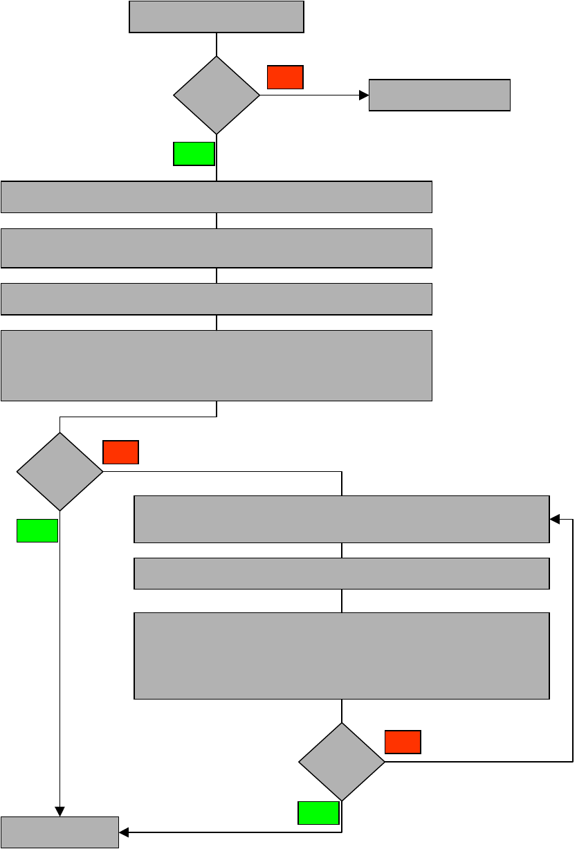
Please refer to process flow OPTIMISATION 4
4
Retrofit instructions Short Sleeve
05/2004 Edition
24
4
Optimisation process
Comp. higher
than 8.5mm?
STOP Optimisation process
Restrictions
fulfilled?
YES
NO
Step 1:
Bind the high component to last machine of the line
Step 2:
All component which are in the placement shadow have to be omitted
at the specific station.
Step 3:
START first optimisation!
Step 4:
Via the first set-up the user has to verify if there are still components in the
placement shadow placed at the specific machine
Restrictions
fulfilled?
Schedule new job
NO
YES
Step 1 :
The components which are still in the placement shadow
have to be omitted on the specific station
Step 2 :
START optimiser!
Step 3:
Compare again if all rstrictions are fulfilled at the specific machine
YES
NO
Retrofit instructions Short Sleeve
05/2004 Edition
25
4.3 Placement of high components
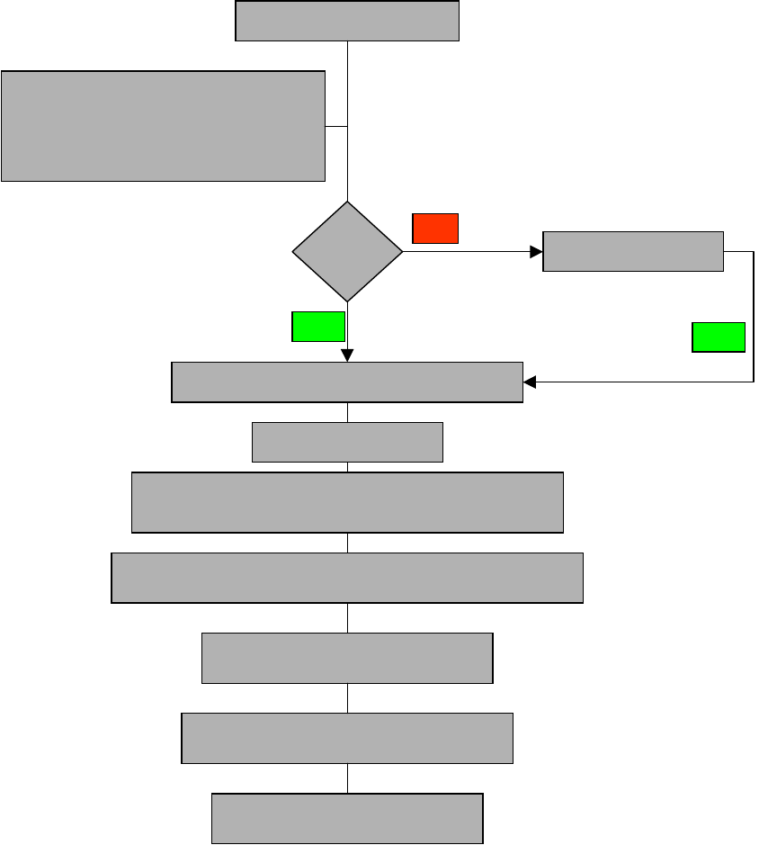
4.3.1 Job schedule / START Production
4
Production START
Job at
the station ?
Job schedule from LCU
YES
NO
Station collecting nozzles automatically
Stop station
Changing manually to single functions / Nozzle configuration
Change dedicated nozzle by using start step function
The special nozzle for the high component is assigned
in the setup/nozzle changer.
Status: Stand. Segment with standard nozzles are o
n the specific RV head.
Manual change of sleeves and nozzles
Starting manually vacuum- and height reference run
Release station for standard production
YES