00192790-01.pdf - 第32页
2 PCB Camera Multicolor (Option) User Manual SIPLACE S-25 HM / HS-50 2.2 Illumination Sett ing Software Version SC.502.xx 11/00 Issue 32 NOTE: Utilize S ection 2 .2 and t he table in Secti on 2.2 .2 to sele ct the b est …
User Manual SIPLACE S-25 HM / HS-50 2 PCB Camera Multicolor (Option)
Software Version SC.502.xx 11/00 Issue 2.2 Illumination Setting
31
2ULHQW DWLRQDO$LGIRU6HOHFWLQJ,OOXPLQDWLRQ
The following table is derived from empirical values and is therefore only to serve as an orienta-
tional aid. A few materials often exhibit very drastic fluctuations (particularly in the case of CEM1),
therefore the best illumination has to be ascertained through testing. In each instance this is done
by selecting the setting for illumination during the course of a sample placement with recognition
of the position of the pertinent PCBs or ceramic substrates.
6HWWLQJWKH,OOXPLQDWLRQ
In case of doubt, the best illumination selection must be ascertained by using the function "Test
the fiducial" or the substrate to be populated.
NOTE:
The processes which must be executed prior to setting the illumination are described in detail in
the section "Teaching Fiducials" or "Teaching Synthetic Fiducials" of the User Manual, Software
version SC 502.xx.
During them, the current substrate or PCB is moved onto the processing belt of the conveyor and
mechanically centered / clamped in place.
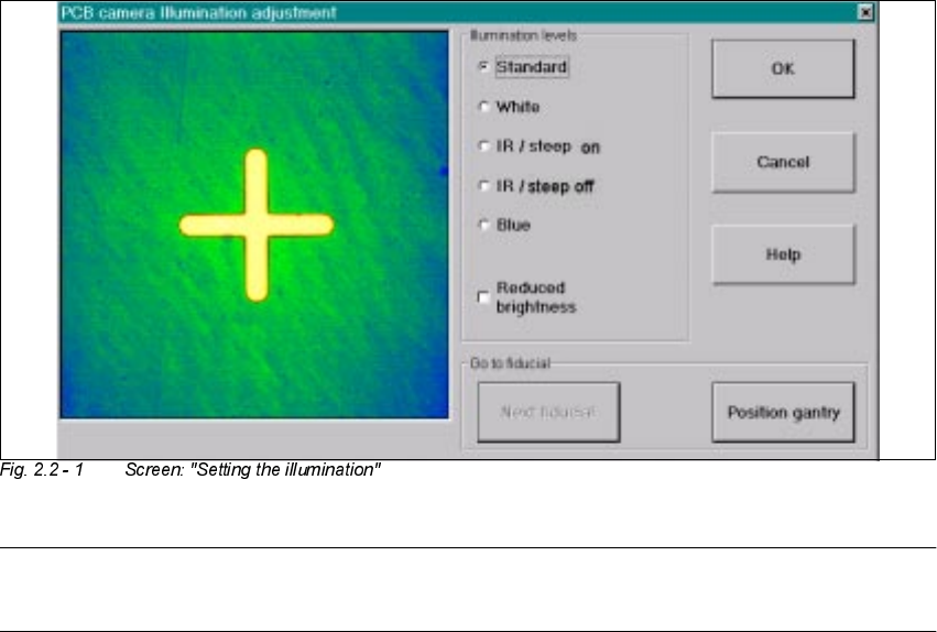
Å Select the ICON "Setting illumination"
Å In the "illumination" menu select the "Setting illumination" button.
The following screen will appear:
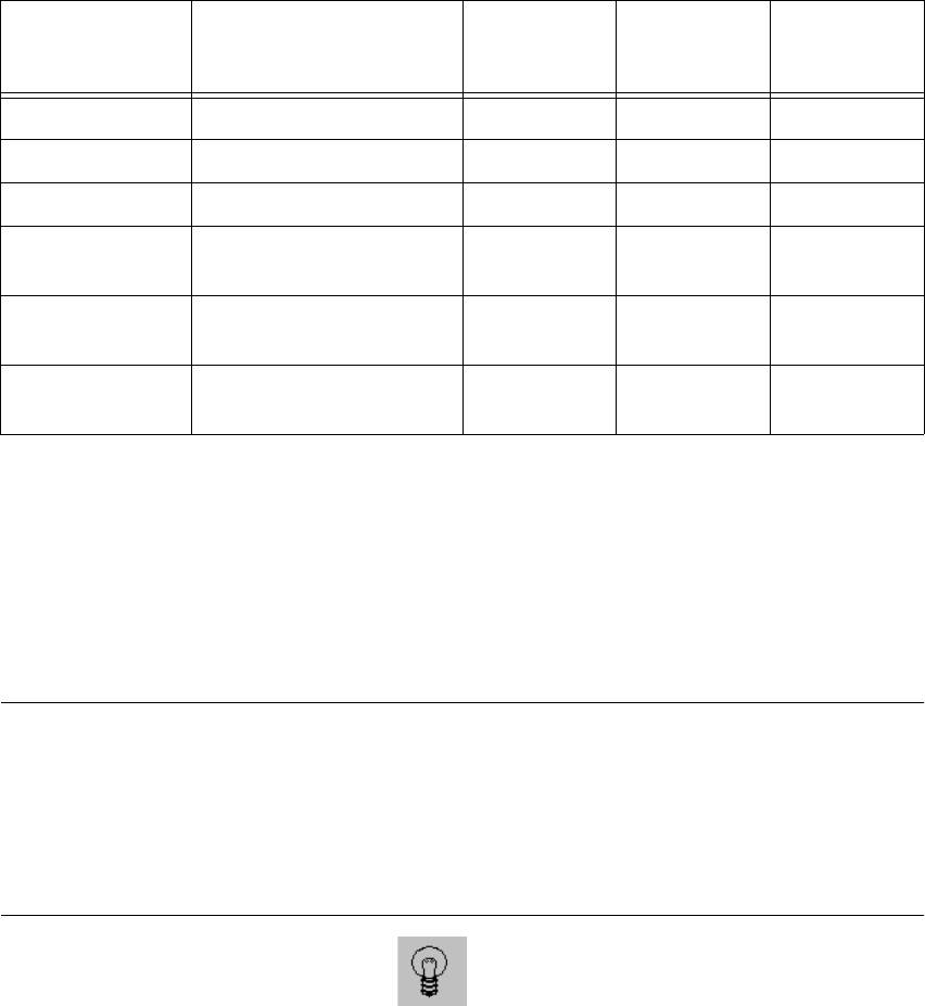
Base material Fiducial material Oblique illu-
mination
BLUE
Infrared
illumination
White illumi-
nation
FR 4 Tin x
Ceramic NiAu, Cu, AgPl x
Ceramic AgPt x
CEM1 Bright copper fiducials,
tin
x
CEM1 Fiducials covered by sol-
der resist
(x) x
Flex on alumi-
num carrier
x
2 PCB Camera Multicolor (Option) User Manual SIPLACE S-25 HM / HS-50
2.2 Illumination Setting Software Version SC.502.xx 11/00 Issue
32
NOTE:
Utilize Section 2.2 and the table in Section 2.2.2 to select the best type of illumination.
Å Select the desired illumination level by activating the pertinent radio button.
Å Select the complete or the reduced brightness by activating or deactivating the rectangular
field.
Å Select the button "Positioning the gantry" and position the gantry over the fiducial that is cur-
rently to be recognized / taught.
Å Check the quality of the image on the vision screen (see the section "Teaching Fiducials" in the
User Manual SC 502.xx).
Å If the image of the fiducial is still not optimal, select another illumination level or, if appropriate,
change the brightness too and select the button "Positioning the gantry" again.
Å If the image of the fiducial is alright, select the button "OK".
As a result, the illumination set is accepted for all 4 gantries (HS-50) or both gantries
(S-25 HM).
User Manual SIPLACE S-25 HM / HS-50 2 PCB Camera Multicolor (Option)
Software Version SC.502.xx 11/00 Issue 2.3 Focus Heigth: Install/Remove the Distance Plate
33
) RFXV+HL JWK ,QVWDOO5HPRYHWKH'LVWDQFH3ODWH
7KLVZLOO DGDSW WKH=SRVLWLRQ RIWKHFDPHUDDQGWKXV WKHIRFXV RIWKH FDPHUDWRWKHWKLFN
QHVVRIWKH&855(17VXEVWUDWHRUWKH&855(173&%WREHSRSXODWHG
DANGER
Only the line engineer or customer’s service engineer trained at Siemens is permitted to remove
and re-install the camera in the manner described below, including carrying out the preparatory
and final steps.
NOTE:
Depending on the thickness of the substrate or PCB, during the installation of the camera it may
be necessary to place the distance plate from the retrofit kit under the camera or not.. This is al-
ways the case with all of the gantries of the machine.
The distance plate will be delivered during the course of the retrofitting of the Multicolor camera
and has already been installed.
The following data items are recommendations to ensure an optimal placement process:
In most cases, adequate imaging quality will still be achieved even it work is done outside the
ranges indicated above.
With the spacer plate removed, system fiducials can still be adequately recognized.
PCB or substrate thickness Focus Install distance plate
(spacer)
0.3 - 3.4 mm 1.7 mm Yes
1.5 - 4.5 mm 3.2 mm No