00192790-01.pdf - 第34页
2 PCB Camera Multicolor (Option) User Manual SIPLACE S-25 HM / HS-50 2.3 Focus Heigth: I nstall/Remove the Distance Plate Software Version SC.502.xx 11/00 I ssue 34 &KH FNL QJW KH6XE VWU DWH7 KLF NQH VVDQ …
User Manual SIPLACE S-25 HM / HS-50 2 PCB Camera Multicolor (Option)
Software Version SC.502.xx 11/00 Issue 2.3 Focus Heigth: Install/Remove the Distance Plate
33
) RFXV+HL JWK ,QVWDOO5HPRYHWKH'LVWDQFH3ODWH
7KLVZLOO DGDSW WKH=SRVLWLRQ RIWKHFDPHUDDQGWKXV WKHIRFXV RIWKH FDPHUDWRWKHWKLFN
QHVVRIWKH&855(17VXEVWUDWHRUWKH&855(173&%WREHSRSXODWHG
DANGER
Only the line engineer or customer’s service engineer trained at Siemens is permitted to remove
and re-install the camera in the manner described below, including carrying out the preparatory
and final steps.
NOTE:
Depending on the thickness of the substrate or PCB, during the installation of the camera it may
be necessary to place the distance plate from the retrofit kit under the camera or not.. This is al-
ways the case with all of the gantries of the machine.
The distance plate will be delivered during the course of the retrofitting of the Multicolor camera
and has already been installed.
The following data items are recommendations to ensure an optimal placement process:
In most cases, adequate imaging quality will still be achieved even it work is done outside the
ranges indicated above.
With the spacer plate removed, system fiducials can still be adequately recognized.
PCB or substrate thickness Focus Install distance plate
(spacer)
0.3 - 3.4 mm 1.7 mm Yes
1.5 - 4.5 mm 3.2 mm No

2 PCB Camera Multicolor (Option) User Manual SIPLACE S-25 HM / HS-50
2.3 Focus Heigth: Install/Remove the Distance Plate Software Version SC.502.xx 11/00 Issue
34
&KHFNLQJWKH6XEVWUDWH7KLFNQHVVDQG$GDSWLQJWKH)RFXV+HLJKW
Whenever the current thickness of substrate or PCB is changed, you must check whether the dis-
tance plate (= spacer) must be installed under the PCB camera Multicolor or removed , as shown
in Fig. 2.3 - 7.
This check can be carried out either on the basis of the table (see above) or, without calculation,
by querying from the line computer (-> Job editor -> Services -> Error messages), as described in
detail in the User Manual for the UNIX line computer SW V502.xx, Section "Configuration of the
PCB camera Multicolor at the Line Computer").
When installed, the space plate is NOT visible. To ascertain whether the spacer place is currently
installed or not, it is therefore necessary to measure the actual distance between the bottom edge
of the PCB camera and the top edge of the conveyor belt (= bottom edge of PCB), as described
below.
Å Determine how thick the PCB or substrate to be processed actually is.
Å Use the above table to determine whether the distance plate is required or not.
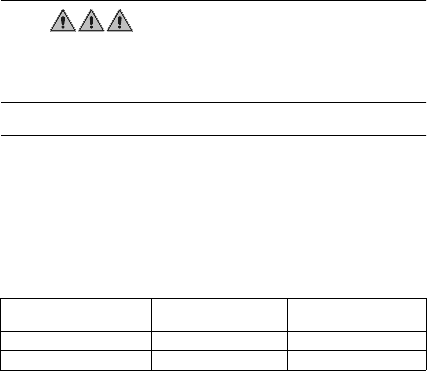
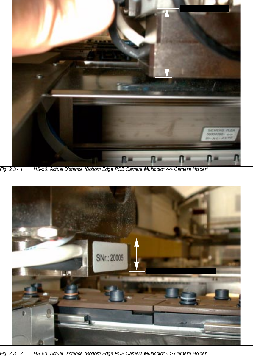
Å Use the sliding calipers to determine the actual distance between the bottom edge of the PCB
camera Multicolor and the bottom edge of the camera holder as shown in Fig.2.3 - 1 and
Fig.2.3 - 2.
Å If a change must be made, remove the PCB camera Multicolor starting from the bottom of the
gantry, proceeding as described below beginning with "Preparatory Steps".
The allocation of camera and gantry must be preserved.
If you detach all the camera´s electrical connections (NOT necessary for this work), you must
use a permanent marker to identify the allocation "camera / gantry".
NOTE:
The brightness balancing of the camera is carried out via the "PC camera board, modular". There-
fore the PCB camera Multicolor and the pertinent "PC camera board, modular" form a mutually
coordinated unit. The parts for cameras and boards are therefore not to be interchanged and - if
faulty - are only to replaced together.
User Manual SIPLACE S-25 HM / HS-50 2 PCB Camera Multicolor (Option)
Software Version SC.502.xx 11/00 Issue 2.3 Focus Heigth: Install/Remove the Distance Plate
35
PPZLWKRXW
GLVWDQFHSODWH
%27720( '*(
VSDFHU
+6
FDPHUDKROGHU
%27720('*(
FDPHUD
PPZLWKRXW
GLVWDQFHSODWHVSDFHU
%27720('*(FDPHUDKROGHU
6+0
%2772 0('*(FDPHUD