00192790-01.pdf - 第36页
2 PCB Camera Multicolor (Option) User Manual SIPLACE S-25 HM / HS-50 2.3 Focus Heigth: I nstall/Remove the Distance Plate Software Version SC.502.xx 11/00 I ssue 36 5H TXLUHG 7 RROV DQG0 DWHULDO V – Allen wrenc…
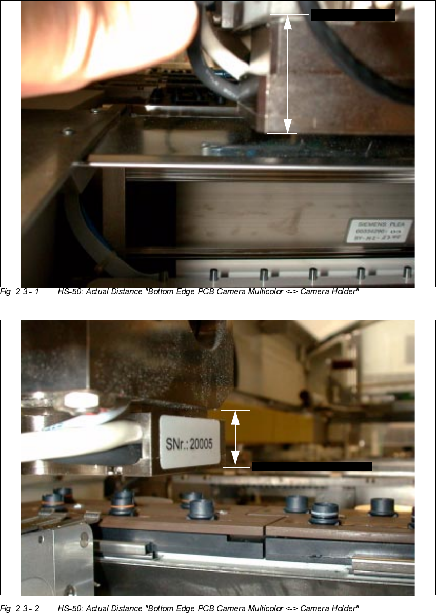
User Manual SIPLACE S-25 HM / HS-50 2 PCB Camera Multicolor (Option)
Software Version SC.502.xx 11/00 Issue 2.3 Focus Heigth: Install/Remove the Distance Plate
35
PPZLWKRXW
GLVWDQFHSODWH
%27720( '*(
VSDFHU
+6
FDPHUDKROGHU
%27720('*(
FDPHUD
PPZLWKRXW
GLVWDQFHSODWHVSDFHU
%27720('*(FDPHUDKROGHU
6+0
%2772 0('*(FDPHUD
2 PCB Camera Multicolor (Option) User Manual SIPLACE S-25 HM / HS-50
2.3 Focus Heigth: Install/Remove the Distance Plate Software Version SC.502.xx 11/00 Issue
36
5HTXLUHG7RROVDQG0DWHULDOV
– Allen wrench, size 2.5
– Oblique-nosed cutting pliers
– Small mirror to be used as an aid while installing/removing the PCB camera Multicolor
– Cable tie L x W = 140 x 3.6 mm Item no.: 00805141-01 3 units / head
– If necessary: Cable clamp, size 6 Item no.: 00805503
(for Placement head S-25 HM)
2

User Manual SIPLACE S-25 HM / HS-50 2 PCB Camera Multicolor (Option)
Software Version SC.502.xx 11/00 Issue 2.3 Focus Heigth: Install/Remove the Distance Plate
37
3UHSDUDWRU\6WHSV
DANGER and Risk of a PLACEMENT HEAD CRASH
Only the line engineer or the customer’s service engineer who have been trained by Siemens is
permitted to remove and install the camera.
Comply with the safety instructions in the section in this User Manual under "Operating Safety".
Also comply with the laser warning instruction for the LED Laser radiation of the PCB camera Mul-
ticolor.
Take note of the warning symbols at the area of the gantries of HS-50: It is DANGEROUS for any-
one wearing a HEART PACEMAKER to come near the linear motors of an HS-50 machine, as
described in detail in the User Manual and in the Service Manual, in the Capter "Special safety
instructions when working in the vicinity of powerfull magnetic fields".
After you have properly carried out the shut-down of the Windows operating system NT:
BEFORE all work the machine must be turned OFF at the main switch and isolated from the
mains. In addition, the compressed air supply must be turned off at the main valve of the com-
pressed air unit in the machine base and the compressed air lines must be bled by actuating the
needle valve at the compressed air unit (particularly due to the risk of injury - posed by residual
air - at the pneumatic cutter after undocking/removing the component changeover table
Obey the applicable accident prevention regulations, DIN standards and special safety codes of
your country at all times. DIN EN 60204 must be adhered to during all work inside the machine
base.
Carry out all work in the order as described below.
The movable component changeover tables must be undocked to permit optimal access to the
placement heads. While doing so, keep in mind that:
The X-gantry must always be moved / pushed out of the area of the component changeover table
before disconnecting the component changeover table.
Otherwise there will be a risk that the placement head may crash!!
High risk of injury exists from the blades and the tape deflector of the cutter, even when the ma-
chine has been turned off.
Never reach into the pneumatic cutter from below or into the empty-tape duct from above, not
even to resolve a problem (e.g., when tape is jammed before the component changeover table is
deinstalled).