00192790-01.pdf - 第43页
User Manual SIPLAC E S-25 HM / HS-50 2 PCB Camera Mu lticolor (Option) Software Version S C.502.xx 11/00 Issue 2.3 Focus Heigth: Install/Remove the Distance Plate 43 DANGER There is add itiona l, higher risk of a ccident…
2 PCB Camera Multicolor (Option) User Manual SIPLACE S-25 HM / HS-50
2.3 Focus Heigth: Install/Remove the Distance Plate Software Version SC.502.xx 11/00 Issue
42
.H\
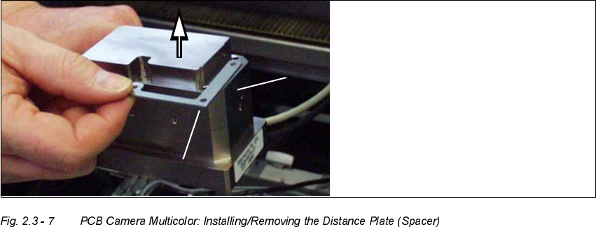
1. PCB camera Multicolor (dismantled)
2. Distance plate (supplied with product or installed while the option is being retrofitted)
Å Remove the distance plate or place it on the camera assembly surface in the correct rotational
position (depends on the holes and the outside contour).
Å Working from below, place the PCB camera Multicolor with or without distance plate, as re-
quired, in the correct position
- on the assembly surface of the camera holder (S-25 HM) or
- on the 3 spacer pieces in the camera holder (HS-50)
Å Screw the camera tight with the 3 captive hex head cap screws M 3 x 14.
Å Fasten the cables leading upward such that the
ORDG
on the plug-type sockets
LVUHOLHYHG
– as shown for HS-50 in Fig. 2.3 - 5.
You will need cable ties or this purpose.
– as show for S-25 HM in Fig. 2.3 - 4.
For this you will require size 6 cable clamps and the M3 and M4 screws removed earlier.
Å Remove all of the tools, etc., from the machine’s working area.

User Manual SIPLACE S-25 HM / HS-50 2 PCB Camera Multicolor (Option)
Software Version SC.502.xx 11/00 Issue 2.3 Focus Heigth: Install/Remove the Distance Plate
43
DANGER
There is additional, higher risk of accident when working with the SITEST program.
The SIPLACE program is only to be started by personnel who are authorized to do so.
For the work with the SITEST program the component changeover table must be moved in and
correctly connected.
Å Start the SITEST program.
Å In the main view, press the button "Total reference run".
Å Afterwards, conduct the calibration:
Whenever the PCB camera Multicolor is reinstalled, all of the placement heads and cameras
must be calibrated - after the overall reference run - as described in the User Manual SITEST
SW V 502.xx.
2 PCB Camera Multicolor (Option) User Manual SIPLACE S-25 HM / HS-50
2.4 LCU: Configuration PCB Camera Multicolor Software Version SC.502.xx 11/00 Issue
44
/&8&RQILJXUDWLRQ3&%&DPHUD0XOWLFRORU
The optional PCB camera Multicolor is selected for SIPLACE 80 S-25 HM or HS-50 in the station
configurator of the UNIX line computer (LCU). Insofar as this operation if concerned it can occur
before or after the PCB camera Multicolor is selected at the station in question, in the SITEST pro-
gram 502.xx.
After the configuration and specification or change of the substrate / PCB thickness (= height) in
the line computers cluster editor, check at the line computer under "Error Messages" (see Section
2.4.2) to ascertain whether it is necessary to adapt / optimize the focus of the PCB camera Multi-
color (see Section 2.3.1) because the spacer (distance plate) has been installed or removed.
6HTXHQFH
Å In the menu bar at the top, select "Services".
Å In the pull-down menu that opens, select the option:
"
6WDWLRQFRQILJXUDWLRQ
".
Å The window from which the machine is selected opens:
Select the machine (HS-50 or S-25 HM) on which the optional PCB camera Multicolor was se-
lected.
Å The "Main view of structure editor" is displayed automatically.
As shown afterwards using the HS-50 for an example, the selected machine (S-25 HM or HS-
50) is displayed graphically, arranged by gantries (1 to 2 or 4), and with the pertinent substruc-
tures (component feeding areas, placement heads, PCB cameras, options, etc.).