00192790-01.pdf - 第51页
User Manual SIPLAC E S-25 HM / HS-50 2 PCB Camera Mu lticolor (Option) Software Version SC.502.xx 11/00 Issue 2.5 SITEST: PCB Camera Multicolor (Option) 51 Å In the menu "PCB fun ctions" select the butt on &quo…
2 PCB Camera Multicolor (Option) User Manual SIPLACE S-25 HM / HS-50
2.5 SITEST: PCB Camera Multicolor (Option) Software Version SC.502.xx 11/00 Issue
50
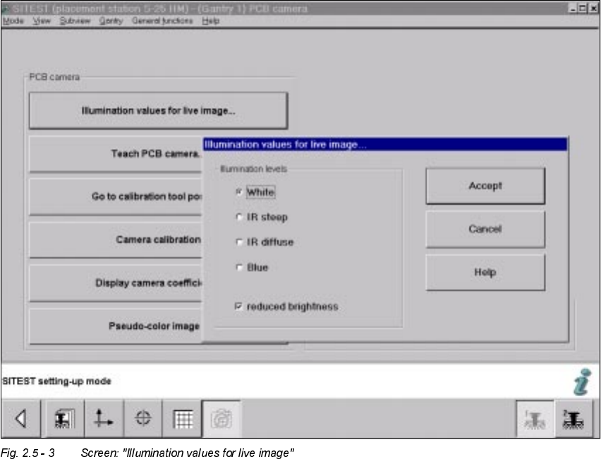
Å The screen "Illumination values for live image" is displayed (using S-25 HM as an example):
Å If the Multicolor camera(s) was (were) retrofitted, reinstalled or exchanged, you must test at
least the illumination levels "White" and "Blue" because their light is visible.
Å Click on the "Radio button" to select the illumination level "White".
Å Deactivate the button "Reduced brightness" and click on the button "Accept".
The complete illumination level is therefore activated at the outset.
Å Switch to the menu "Teach PCB camera" -> Click on the button "PCB camera":
Make a visual check (with safety hoods closed):
The camera’s white light must must flash.
Å Once again, press the button "Illumination values for live image".
Å Now activate the option "Reduce illumination".
This reduces the illumination level by one-half.
Å Click on the button "Accept" again.
Make a visual check (with the safety hoods closed):
The camera’s white light must must flash repeatedly but not as brightly as before.
Å Execute the above-described check for illumination level "blue" as well.
Å Exit the menu "(Gantry 1) PCB camera".

User Manual SIPLACE S-25 HM / HS-50 2 PCB Camera Multicolor (Option)
Software Version SC.502.xx 11/00 Issue 2.5 SITEST: PCB Camera Multicolor (Option)
51
Å In the menu "PCB functions" select the button "PCB camera" of gantry 2 or 3 or 4 at the HS-
50 or gantry 2 at S-25 HM.
One after the other, perform the above-described operation for these PCB cameras Multicolor.
NOTE:
If you would like to check the IR illumination levels too, perform the above-described operation in
a like manner for these levels also. Place a white sheet of paper under the camera. As a check,
switch over to the vision screen in each case.
Å If you would then like to look at a specific position on the vision screen with the camera(s) or
to determine their precise X-Y position, change to the menu "Teach the PCB camera" in the
basic view.
Å Carry out the additional steps as described in User Manual SC V502.xx under "Teach the
fiducials".
Å After the illumination test, check the "focus of camera / thickness of substrate" (Section 2.4.2)
and then set the illumination at the station for the substrate to be placed currently (see Section
2.2.3).
q
2 PCB Camera Multicolor (Option) User Manual SIPLACE S-25 HM / HS-50
2.5 SITEST: PCB Camera Multicolor (Option) Software Version SC.502.xx 11/00 Issue
52