00193360-02.pdf - 第21页
Retrofitting Instructions S plice Detection Basic Package S/F 11/2003 Edition 21 13 T ools – Metric hex ball en d wrench Set (also c alled “Alle n” wrench) – Diagon al cutters – #1 Cros s Point s crewdriv er (also called…
Retrofitting Instructions Splice Detection Basic Package S/F
11/2003 Edition
20
12 Safety Instructions
12
DANGER
All the work described below must only be carried out by Siemens service engineers. 12
The safety instructions from the “Operational safety” chapter of the user manual or the ervice ma-
nual take precedence over these instructions. 12
SIPLACE placement machines are supplied main power voltage. Consequently parts of these sy-
stems carry dangerous voltages inside the machine frame, even when switched off at the main
switch. 12
Before starting any work switch the machine off at the main switch and disconnect it from the main
power supply. 12
Always follow the accident prevention regulations, DIN or other standards and special safety rules
applicable in your country. Always follow DIN EN 60204 and DIN VDE 105-100 when working in-
side the machine frame. 12
Pay attention to the information concerning residual voltages and electrostatic discharge (ESD) in
the Operating safety chapter. 12
During the retrofit, always secure the machine to prevent access by other people and to prevent
it being switched on again. 12
If the component cart is out of the machine or is not correctly coupled to the machine, do not con-
nect it electrically to the machine frame. 12
12
12.1 Definitions
DANGER
in terms of these instructions means that death, severe bodily injury or considerable material
damage WILL occur if the instructions about danger are not followed. 12
12
NOTE 12
12
12
Retrofitting Instructions Splice Detection Basic Package S/F
11/2003 Edition
21
13 Tools
– Metric hex ball end wrench Set (also called “Allen” wrench)
– Diagonal cutters
– #1 Cross Point screwdriver (also called a “Phillips Head” screwdriver)
– A small flat bladed screwdriver
14 Parts
Contents Splice Detection Basic Package S / F
(item no.: 00116935-xx) 14
Pieces Description Item no.:
- 1 Retrofitting Instructions Basic Package 00193360-01
- 1 Retrofitting Instructions Table Controller 00193361-01
- 1 Retrofitting Instructions Splice Sensor 2x8 mm 00193365-01
- 1 Hub Unit 00366091-02
- Various installation material
- 1 Cable Hub - TC long 00368249-01
- 1 Cable Hub - TC short 00368250-01
- Cable Power Supply HUB 00368322-01
- 1 Serial Cable to station computer 00368431-01
- Machine Cover 1 modified 00368324-01
- 1 Machine Cover 2 modified 00368553-01
15 Preparation
: Pull out all feeder tables
: Switch the machine off at the main switch.
: Interrupt the power supply to the machine to prevent the risk of electric shock.
: Read the installation instructions carefully.
Retrofitting Instructions Splice Detection Basic Package S/F
11/2003 Edition
22
16 Installing the HUB
16
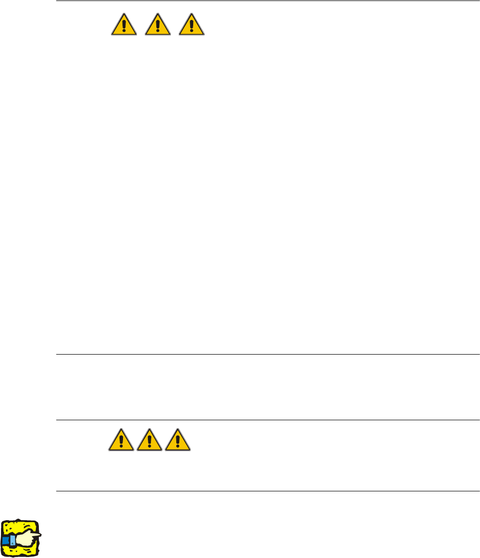
Fig. 16 - 1 Notes on installing the HUB
: The hub is fitted beneath the side panel of the input conveyor (Fig. 6 - 1 left).
: Loosen the screws for fixing the contact plug of the input conveyor (Fig. 6 - 1 right).
DANGER
Before starting the placement machine connect and bolt the HUB electrical conducting with the
machine frame! 16
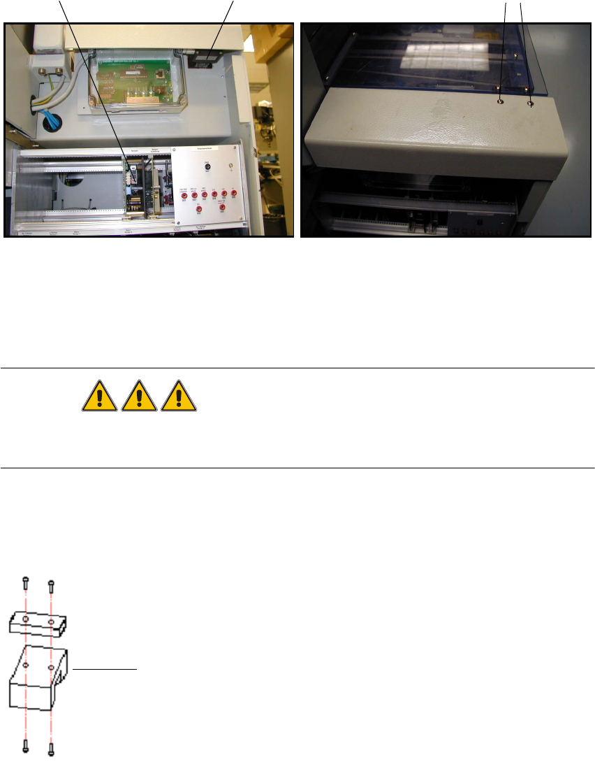
: Replace the spacer with the mount for the hub, then reinstall the hub and contact plug (Fig. 6
- 2). Don't forget to adjust the contact plug afterwards.
16
Fig. 16 - 2 Contact plug and spacer
Servo unit
5x10 screws
Contact plug
Spacer