00193360-02.pdf - 第24页
Retrofitting Instructions Splice Detection B asic Package S /F 11/2003 Edition 24 17.1 Connecting location 1 to HUB : Open the door to the servo unit and de tach it from its mo unt. 17 First detach the groundin g cable f…
Retrofitting Instructions Splice Detection Basic Package S/F
11/2003 Edition
23
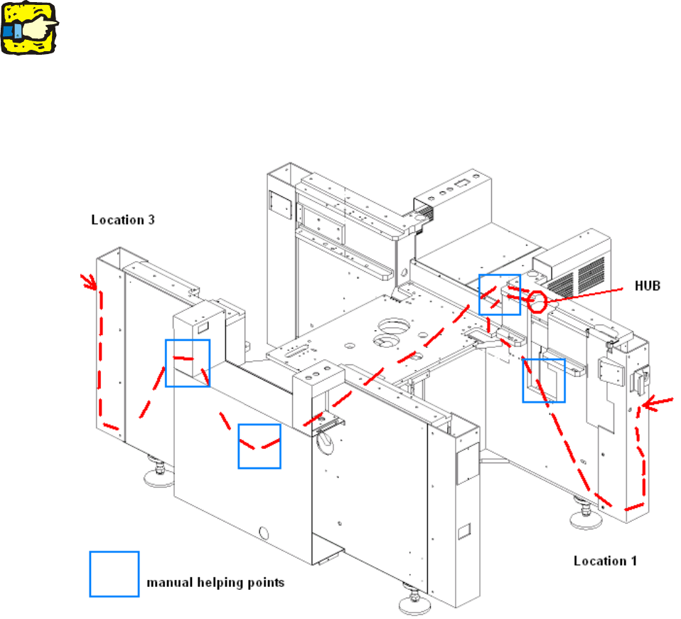
17 Cable route
The following diagram (Fig. 7 - 1) shows the route that the cables should follow from the table con-
trollers to the hub. 17
17
Please use the pilot wire to help you through difficult sections. 17
17
17
The figure shows a number of manual helping points, i.e. points at which you can reach the cable
with your hand. 17
17
Fig. 17 - 1 Cable route through the machine
17
17
17
Retrofitting Instructions Splice Detection Basic Package S/F
11/2003 Edition
24
17.1 Connecting location 1 to HUB
: Open the door to the servo unit and detach it from its mount.
17
First detach the grounding cable fixed to the inside of the door. 17
17
17
: Remove the screw that secures the servo unit, and pull the unit out of its drawer.
: Loosen the 6 screws to remove the U-profile at location 1.
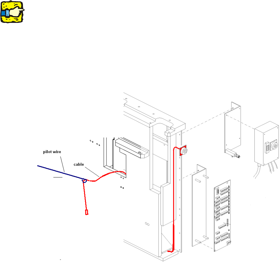
: Then fix the narrow end of the cable to the pilot wire, and pull it through the opening in the base
frame (see Fig. 7 - 2).
17
Fig. 17 - 2 Procedure for running the Cat5 cable to the hub
: Replace the U-profile (panel) with the U-profile supplied (which has the additional opening for
the socket for connecting the splice detector).
: Fix the cable to the HUB using 4xM3 screws provided.
17
17
Retrofitting Instructions Splice Detection Basic Package S/F
11/2003 Edition
25
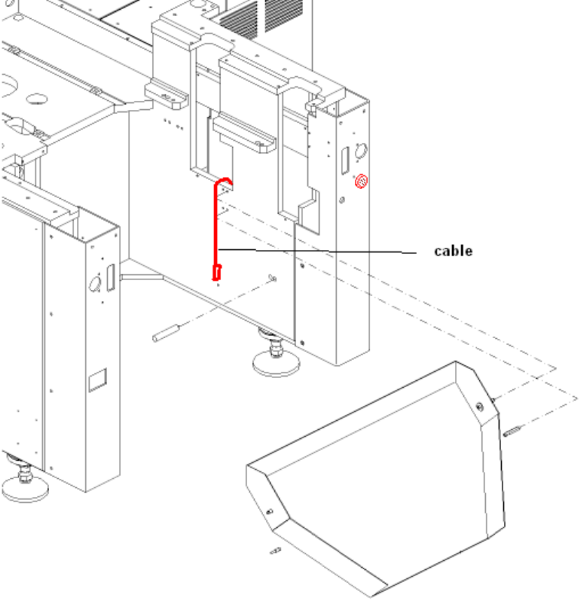
: Pull the cable through the base frame to the HUB using the pilot wire (Fig. 7 - 3, 7 - 4, 7 - 5).
: Fix the new U-profile to the machine base frame (Fig. 7 - 3).
. 17
Fig. 17 - 3 Fitted cable and U-profile