00193360-02.pdf - 第27页
Retrofitting Instructions S plice Detection Basic Package S/F 11/2003 Edition 27 17.2 Connecting location 3 to the HUB : Check on ce again that yo u have di sconnec ted the statio n from the power su pply . : Remove th e…
Retrofitting Instructions Splice Detection Basic Package S/F
11/2003 Edition
26
17
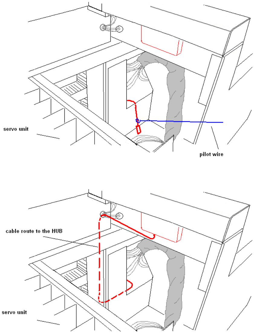
Fig. 17 - 4 Cable route to the HUB
17
Fig. 17 - 5 Cable route to the HUB
17

Retrofitting Instructions Splice Detection Basic Package S/F
11/2003 Edition
27
17.2 Connecting location 3 to the HUB
: Check once again that you have disconnected the station from the power supply.
: Remove the cover from the power supply unit.
17
First detach the grounding cable fixed to the inside of the cover. 17
17
17
: Remove the screw that secures the power supply unit, and pull the unit out of its drawer care-
fully.
: Loosen the 6 screws to remove the U-profile at location 3.
: Then fix the narrow end of the cable to the pilot wire, and pull it as far as the opening on the Y
axis motor (as for the connection for location 1).
: Replace the U-profile (panel) with the U-profile supplied (which has the additional opening for
the socket for connecting the splice detector).
: Fix the cable to the HUB using the 4x M3 screws provided.
17
17
17
17
17
17
17
17
17
17
17
17
17
17
17
17
17
Retrofitting Instructions Splice Detection Basic Package S/F
11/2003 Edition
28
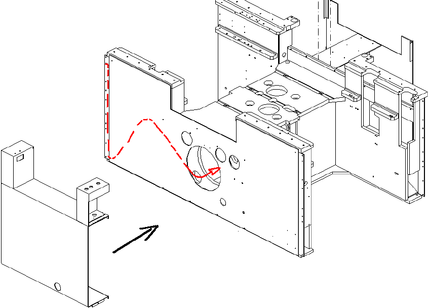
: Pull the cable further to the opening between the power supply drawer unit and the machine
frame (Fig. 7 - 6).
17
Fig. 17 - 6 Diagram of the cable route to location 3
: Pull the cable through the machine to the opening in the servo drawer unit, and on to the hub
(as for the connection for location 1).
: Fix the new U-profile at the machine.