Vakuumtooling an HS60.pdf - 第35页
Special design 2 Assembly in structions Special design Vacuum tooling SIPLACE HS-60 10/2006 Edition 35 2.7 Safety instructions WA R N IN G The safety instructions from the “Operational safe ty” chapter of the user manual…

2 Assembly instructions Special design Vacuum tooling SIPLACE HS-60 Special design
10/2006 Edition
34
2.4 Possible variations
– The shape and size of the vacuum tooling might varies for different PCB’s.
– For dual conveyor machines, the installation for the second conveyor is identical with the first
conveyor installation. The only changing is that the vacuum devices have to be fitted sideways
on the machine base and not on the lifting table.
2.5 Scope of delivery
2
For dual conveyor the following material has to be delivered twice. 2
2
2
Independent from the conveyor type 2
2.6 Necessary tools
– Set of allen keys
– Set of screw drivers
–Wire cutter
– Hose cutter
– Cable ties
– Clue pads for cable ties
2
2x
Option lifting tables (SC 00367190-xx/DC 00367189-xx)
2x
Vacuum toolings with vacuum devices
8x
Spacer for lifting limitation 3,2mm (03013648-xx)
2x
Screws M4x16mm
1x
PUN 8 – hose, approx. 5m
1x
PUN 10 – hose, approx. 2m
1x
New cover plate for the maintenance unit
1x
Maintenance unit (00176066-xx)
1x
Assembly instruction

Special design 2 Assembly instructions Special design Vacuum tooling SIPLACE HS-60
10/2006 Edition
35
2.7 Safety instructions
WARNING
The safety instructions from the “Operational safety” chapter of the user manual and servicing in-
structions take precedence over these instructions. 2
The SIPLACE placement machines are supplied with mains voltage.
Consequently parts of these systems carry dangerous voltages! This voltage is present at certain
modules inside the machine base, even when the machine is switched off at the main power
switch.
Incorrect handling of the placement machine or touching live parts of the machine can result in
death or severe injury, and considerable damage to equipment.
BEFORE starting any work, shut down the operating system correctly, then switch the machine
OFF at the main power switch and disconnect from the main power supply. In addition, the com-
pressed air supply must be switched off at the compressed air unit's main valve in the machine
base and vented by actuating the needle valve on the compressed air unit.
There is DANGER for heart pacemaker wearers in the vicinity of the linear motors, as described
in detail in the "Special safety instructions for working in the vicinity of strong magnetic fields"
section of the user manual and service manual.
Always follow the accident prevention regulations, DIN or other standards and special safety
rules applicable in your country.
Pay attention to the information concerning residual voltages in the Operational Safety chapter.
Follow the ESD regulations as described in the operational safety section of the operating
instructions.
During the retrofit, always secure the machine to prevent access by other people and to prevent
it being switched on again. The procedure is described in the “Locking the machine…” section of
the user manual.
Working with the SITEST program further increases the risk of accident.
The SITEST program must only be used by authorized and trained personnel.
2
2.7.1 Definitions
2
Note 2
2
2
2 Assembly instructions Special design Vacuum tooling SIPLACE HS-60 Special design
10/2006 Edition
36
2.8 Working principle with circuit diagrams
If the plugs X34 and X35 are plugged in on the conversion board and the switch is on, the option
is activated and the signal lines can be evaluated accordingly. The plugs only have to be plugged
when the machine is switched off. 2
When the vacuum reaches the upper level the placement process is enabled. If the level is not
reached, an error will appear at the GUI. 2
After the placement process is finished, the vacuum will be relieved. Not until the lower level is
reached the lifting table will drive down. 2
2.8.1 Connection, working principle and programming of the vacuum sensor
2.8.1.1 Connection of the vacuum sensor
The electrical connection takes place with the conversion board at the plugs X34(PA1) and
X35(PA2). 2
The board is located in the intermediate conveyor of the machine. 2
2
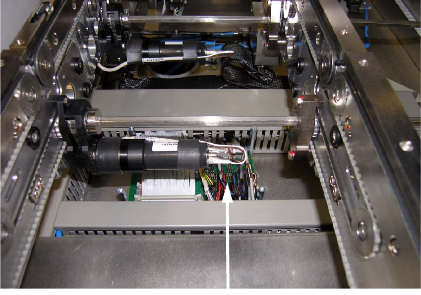
Conversion board