Vakuumtooling an HS60.pdf - 第37页
Special design 2 Assembly in structions Special design Vacuum tooling SIPLACE HS-60 10/2006 Edition 37 2 2 If the vacuum generato r is mounted on the lif ting t able the tot al conveyor wid th is limited. For dual convey…
2 Assembly instructions Special design Vacuum tooling SIPLACE HS-60 Special design
10/2006 Edition
36
2.8 Working principle with circuit diagrams
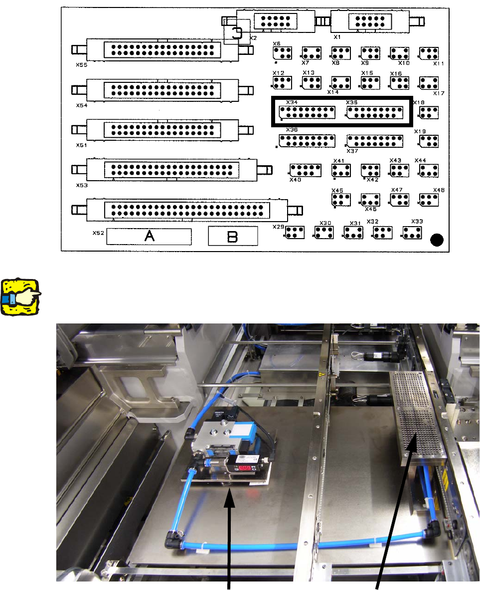
If the plugs X34 and X35 are plugged in on the conversion board and the switch is on, the option
is activated and the signal lines can be evaluated accordingly. The plugs only have to be plugged
when the machine is switched off. 2
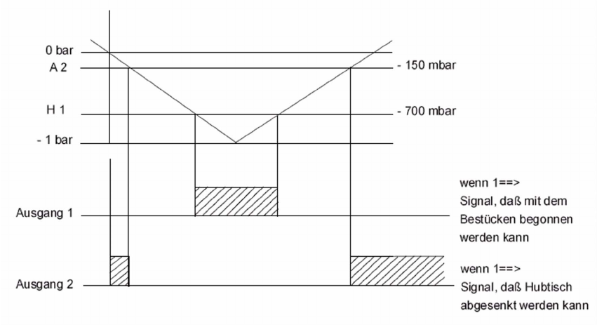
When the vacuum reaches the upper level the placement process is enabled. If the level is not
reached, an error will appear at the GUI. 2
After the placement process is finished, the vacuum will be relieved. Not until the lower level is
reached the lifting table will drive down. 2
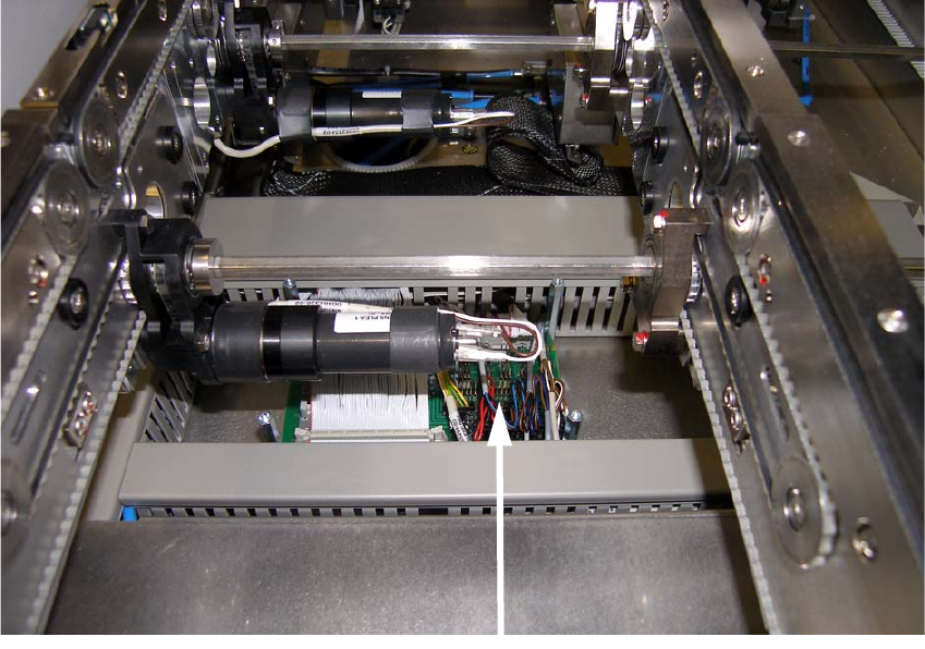
2.8.1 Connection, working principle and programming of the vacuum sensor
2.8.1.1 Connection of the vacuum sensor
The electrical connection takes place with the conversion board at the plugs X34(PA1) and
X35(PA2). 2
The board is located in the intermediate conveyor of the machine. 2
2
Conversion board
Special design 2 Assembly instructions Special design Vacuum tooling SIPLACE HS-60
10/2006 Edition
37
2
2
If the vacuum generator is mounted on the lifting table the total conveyor width is limited. For dual
conveyor the vacuum generator has to be mounted sideways at the pedestal next to the conveyor.2
2
Vacuum generator
Vacuum tooling
2 Assembly instructions Special design Vacuum tooling SIPLACE HS-60 Special design
10/2006 Edition
38
The switch for activating and deactivating of the option has to be mounted on the top of the cover
plate of the conversion board. 2
2.8.1.2 Working principle of the vacuum sensor
If the set vacuum level is not reached, the placement process cannot be started. 2
After finishing the placement process the vacuum has to relieve until the set level is reached, be-
fore the lifting table can drive down. 2
The thresholds are only checked directly after the lifting table drove up or drove down. 2
A drop in the vacuum pressure during the placement process will not be detected. 2
The set vacuum levels can vary depending on the size and layout of the PCB. 2
2
2
2
2
2
2
2
2
2