Vakuumtooling an HS60.pdf - 第44页
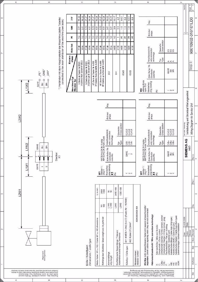
2 Assembly instructions Special design Va cuum tooling SIPLACE H S-60 Special design 10/2006 Edition 44 2.8.2.2 Circuit diagram of the maintenance unit 2
Special design 2 Assembly instructions Special design Vacuum tooling SIPLACE HS-60
10/2006 Edition
43
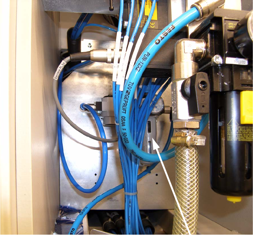
2.8.2 Installation and connection of the maintenance unit
2.8.2.1 Installation of the maintenance unit
The maintenance unit has to be mounted onto the delivered plate behind the pneumatic unit. 2
: Remove the existing plate behind the pneumatic unit and change it for the delivered.
: Mount the delivered maintenance unit onto the plate.
2
2
2
Maintenance unit
2 Assembly instructions Special design Vacuum tooling SIPLACE HS-60 Special design
10/2006 Edition
44
2.8.2.2 Circuit diagram of the maintenance unit
2
Special design 2 Assembly instructions Special design Vacuum tooling SIPLACE HS-60
10/2006 Edition
45
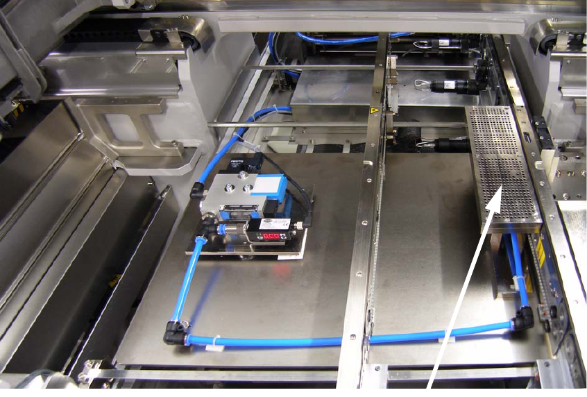
2.8.3 Installation of the option lifting tables
: Unscrew the 4 screws from the existing lifting table and remove the table carefully.
: Lift the option lifting table carefully into the machine and tighten it with the 4 screws you remo-
ved before.
2.8.4 Installation of the vacuum toolings
: Put the vacuum tooling onto the lifting table and position it at the right place. There are two pins
on the lifting table to help you find the right positon.
: Tighten the tooling with one screw to the lifting table.
2
2
2
2
2
2
Vacuum tooling