Vakuumtooling an HS60.pdf - 第45页
Special design 2 Assembly in structions Special design Vacuum tooling SIPLACE HS-60 10/2006 Edition 45 2.8.3 Inst allation of the option lif ting t ables : Unscrew the 4 screws from the existing lifting t able and remove…
2 Assembly instructions Special design Vacuum tooling SIPLACE HS-60 Special design
10/2006 Edition
44
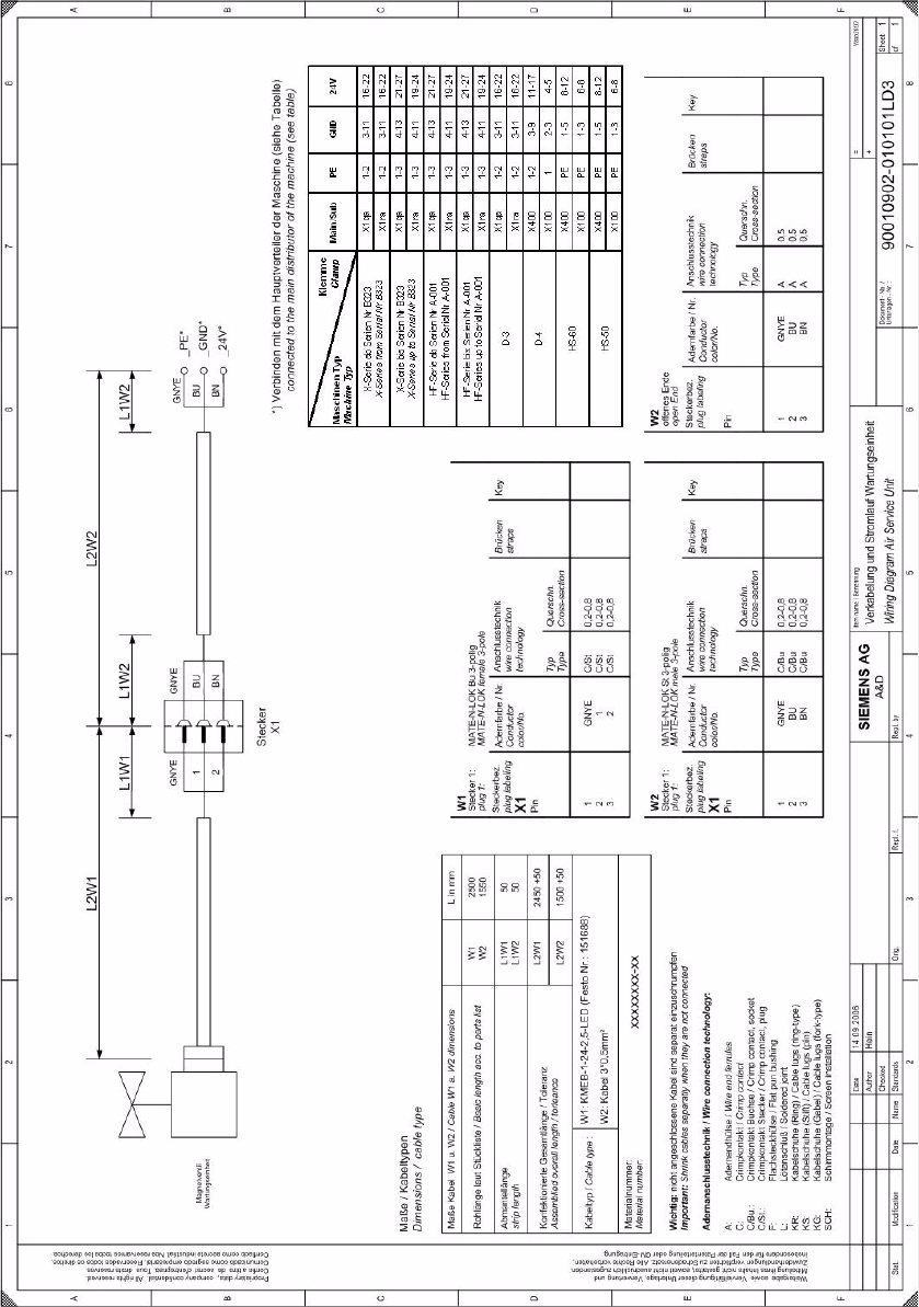
2.8.2.2 Circuit diagram of the maintenance unit
2
Special design 2 Assembly instructions Special design Vacuum tooling SIPLACE HS-60
10/2006 Edition
45
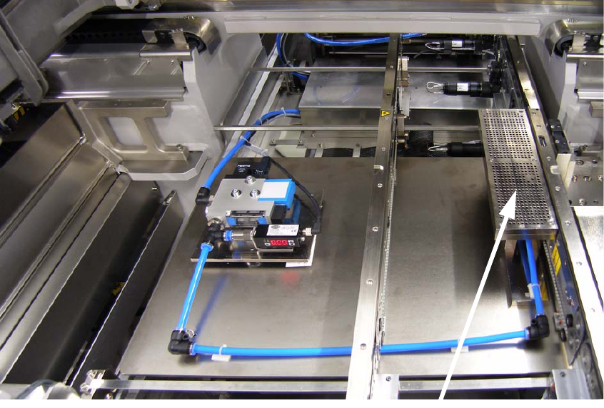
2.8.3 Installation of the option lifting tables
: Unscrew the 4 screws from the existing lifting table and remove the table carefully.
: Lift the option lifting table carefully into the machine and tighten it with the 4 screws you remo-
ved before.
2.8.4 Installation of the vacuum toolings
: Put the vacuum tooling onto the lifting table and position it at the right place. There are two pins
on the lifting table to help you find the right positon.
: Tighten the tooling with one screw to the lifting table.
2
2
2
2
2
2
Vacuum tooling
2 Assembly instructions Special design Vacuum tooling SIPLACE HS-60 Special design
10/2006 Edition
46
2
2
Vacuum tooling
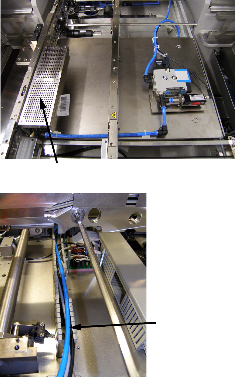
Hose- and cable layout