Vakuumtooling an HS60.pdf - 第55页
Special design 2 Assembly in structions Special design Vacuum tooling SIPLACE HS-60 10/2006 Edition 55 2.10 Conveyor firmware 2.10.1 Working principle The two ou tputs of the vacu um sensor are sample d by the conveyer f…
2 Assembly instructions Special design Vacuum tooling SIPLACE HS-60 Special design
10/2006 Edition
54
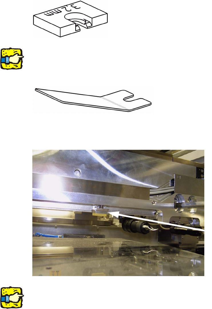
2.9 Installation of the spacers in the conveyor
The spacers avoid a clamping of the PCB. 2
2
2
If the vacuum tooling will be removed, to produce other PCB’s, the 8 spacers also have to be re-
moved. 2
With the delivered tool the spacers are easy to fit. 2
2
: Push the tool under the spring and lift the spring gently.
: Push in one spacer per actuator. There are 4 spacers per processing area and conveyor line.
2
2
For removing the spacers follow the instructions in inverted direction. 2
2
Spacer

Special design 2 Assembly instructions Special design Vacuum tooling SIPLACE HS-60
10/2006 Edition
55
2.10 Conveyor firmware
2.10.1 Working principle
The two outputs of the vacuum sensor are sampled by the conveyer firmware. If the two signals
“lifting table up” and “vacuum on” are present, the placement process will be enabled. After the
placement process it will be checked if the vacuum is completely relieved. Not until that is true,
the lifting table will drive down and the PCB will be moved. 2
2.10.2 Setting the conveyor firmware with Hyperterminal
: Connect your computer with the conveyor controller with a serial cable (1:1 – cable)
: Start the program on the delivered CD “Ip-transport.ht” with a double-click.
2
Hauptmenue Transport Siplace HS60 2
Trace-Meldungen aus: 'Strg'+'A', ein: 'Strg'+'E' 2
1 - Bug-Report 2
2 - Transport Info 2
3 - Einstellen Meldungen 2
4 - Steuerplatine 2
5 - Einzelkomponenten 2
6 - Dauerlauf 2
7 - Firmware-Test 2
8 - Koppeln Barcode-Schnittstelle 2
9 - parameter 2
2
parameter 2
1 - list parameter 2
2 - modify parameter 2
3 - save to EEPROM 2
0 - quit 2
parameter track 1 2
1, 6, // version 2
10, 500, // [mm/s] maximum velocity conveyor 2
11, 350, // [mm/s] velocity drive-in machine 2
12, 350, // [mm/s] velocity drive-out machine 2
13, 50, // [0.1m/s²] maximum acceleration 2
14, 60, // [mm/s] velocity laser-light barrier 2

2 Assembly instructions Special design Vacuum tooling SIPLACE HS-60 Special design
10/2006 Edition
56
15, 25, // [0.1m/s²] deceler.laser-light barrier 2
16, 350, // [mm/s] velocity sensor laser-light 2
20, 0, // barcode scanner 2
21, 0, // ceramic centering unit 2
22, 0, // optional stopper 2
23, 0, // type vacuum tooling = AVSP 2
24, 0, // no verification of clamping with motor 2
41, 0, // left side fixed, width adjustment 2
43, 0, // fixed rails pitch (actual) 2
44, 0, // fixed rails pitch (target) 2
42, 0, // extendend region width adjustment 2
48, 100, // [%] force stepping motor width adj. 2
49, -413, // [um] offset width adjustment 2
50, -969, // [um] offset fixed rail 2
47, 1, // position fixed rail ok 2
60, 855, // [um] calibration position 1, width adj. 2
61, 48315, // [um] calibration position 2, width adj. 2
62, 220, // [um] cavity driver, input, width adj. 2
63, -39, // corr. a0, sensor width adj., input 2
64, 42, // corr. a1, sensor width adj., input 2
65, 48, // corr. a2, sensor width adj., input 2
66, 207, // [um] cavity driver, output, width adj. 2
67, -11, // corr. a0, sensor width adj., output 2
68, -27, // corr. a1, sensor width adj., output 2
69, -2, // corr. a2, sensor width adj., output 2
70, 0, // [um] cavity driver, middle, width adj. 2
71, 0, // corr. a0, sensor width adj., middle 2
72, 0, // corr. a1, sensor width adj., middle 2
73, 0, // corr. a2, sensor width adj., middle 2
80, 60, // [mm/s] velocity stopper 2
81, 350, // [mm/s] velocity sensor stopper 2
82, 25, // [0.1m/s²] deceleration stopper 2
83, 600, // [ms] drive-up time stopper 2
84, 60, // [mm/s] velocity stopper LBO 2
85, 300, // [mm/s] velocity sensor LBO 2
86, 25, // [0.1m/s²] deceleration stopper LBO 2
87, 600, // [ms] drive-up time stopper LBO 2
2
2