Vakuumtooling an HS60.pdf - 第59页
Special design 2 Assembly in structions Special design Vacuum tooling SIPLACE HS-60 10/2006 Edition 59 2.1 1 Inst allation of the cover for the laser light barrier (option) For very thin PCB’ s (<0,3mm) the diff usion…
2 Assembly instructions Special design Vacuum tooling SIPLACE HS-60 Special design
10/2006 Edition
58
24, 0, // no verification of clamping with motor 2
41, 0, // left side fixed, width adjustment 2
43, 0, // fixed rails pitch (actual) 2
44, 0, // fixed rails pitch (target) 2
42, 0, // extendend region width adjustment 2
48, 100, // [%] force stepping motor width adj. 2
49, -413, // [um] offset width adjustment 2
50, -969, // [um] offset fixed rail 2
47, 1, // position fixed rail ok 2
60, 855, // [um] calibration position 1, width adj. 2
61, 48315, // [um] calibration position 2, width adj. 2
62, 220, // [um] cavity driver, input, width adj. 2
63, -39, // corr. a0, sensor width adj., input 2
64, 42, // corr. a1, sensor width adj., input 2
65, 48, // corr. a2, sensor width adj., input 2
66, 207, // [um] cavity driver, output, width adj. 2
67, -11, // corr. a0, sensor width adj., output 2
68, -27, // corr. a1, sensor width adj., output 2
69, -2, // corr. a2, sensor width adj., output 2
70, 0, // [um] cavity driver, middle, width adj. 2
71, 0, // corr. a0, sensor width adj., middle 2
72, 0, // corr. a1, sensor width adj., middle 2
73, 0, // corr. a2, sensor width adj., middle 2
80, 60, // [mm/s] velocity stopper 2
81, 350, // [mm/s] velocity sensor stopper 2
82, 25, // [0.1m/s²] deceleration stopper 2
83, 600, // [ms] drive-up time stopper 2
84, 60, // [mm/s] velocity stopper LBO 2
85, 300, // [mm/s] velocity sensor LBO 2
86, 25, // [0.1m/s²] deceleration stopper LBO 2
87, 600, // [ms] drive-up time stopper LBO 2
2
2
2
2
2
2
2
Special design 2 Assembly instructions Special design Vacuum tooling SIPLACE HS-60
10/2006 Edition
59
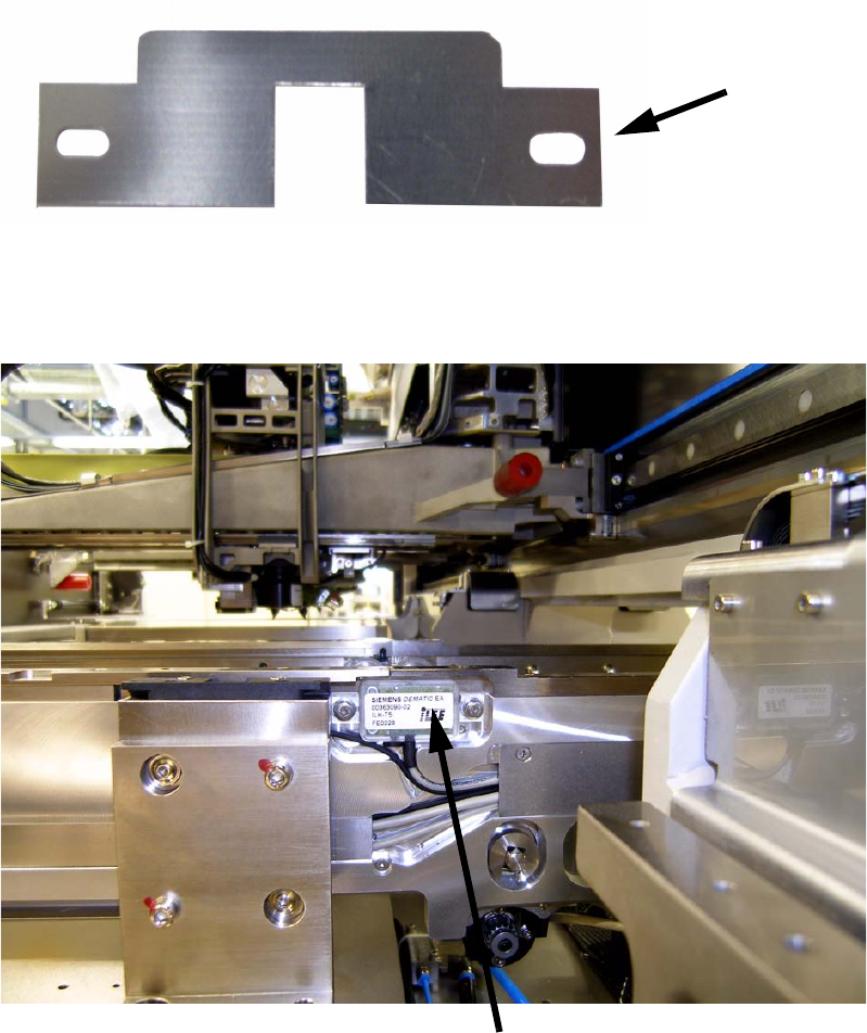
2.11 Installation of the cover for the laser light barrier
(option)
For very thin PCB’s (<0,3mm) the diffusion of the laser beam is to much and the PCB cant be de-
tected. With the cover this effect will be improved. 2
2
2
: Remove the two screws on the light barrier to remove the light barrier.
2
Cover
Laser light barrier
2 Assembly instructions Special design Vacuum tooling SIPLACE HS-60 Special design
10/2006 Edition
60
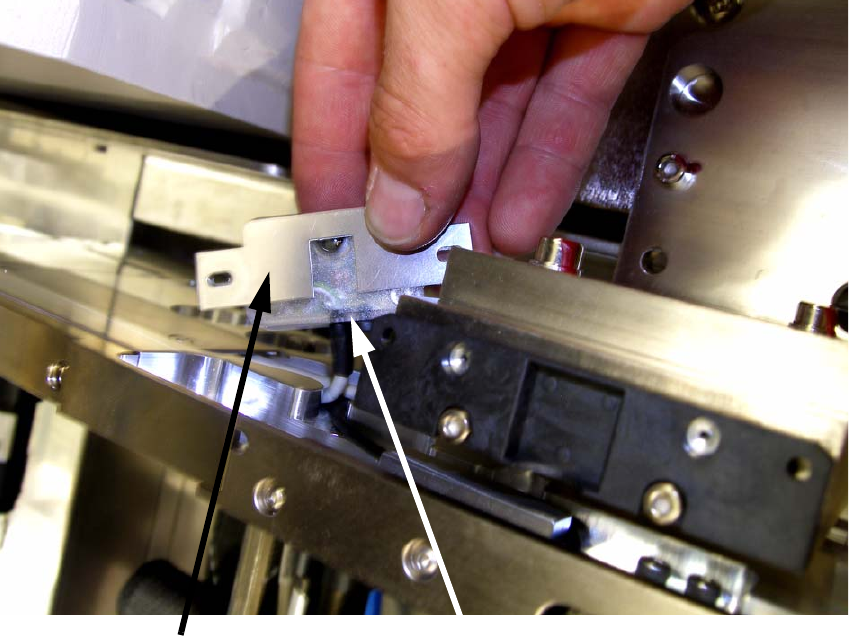
: Put the cover onto the light barrier as shown at the picture below and mount the light barrier
back to its original place with the two screws.
2
2
2
2
Laser light barrier
Cover