CP45FVNEO Maintenance Reference (Eng, Ver3).pdf - 第126页
Samsung Component Placer CP45NEO Series Maintenance Guide OUTPUT PIN NO. DEF. DESCRIPTION REMARK 1~16 OUT1.0~1.7 FEEDER SOL #1~#8 17~32 OUT2.0~2.7 FEEDER SOL #9~#16 33~48 OUT3.0~3.7 FEEDER SOL #17~#24 CN5 49~56 OUT4.0~…
Inspection of the Controller
7-17
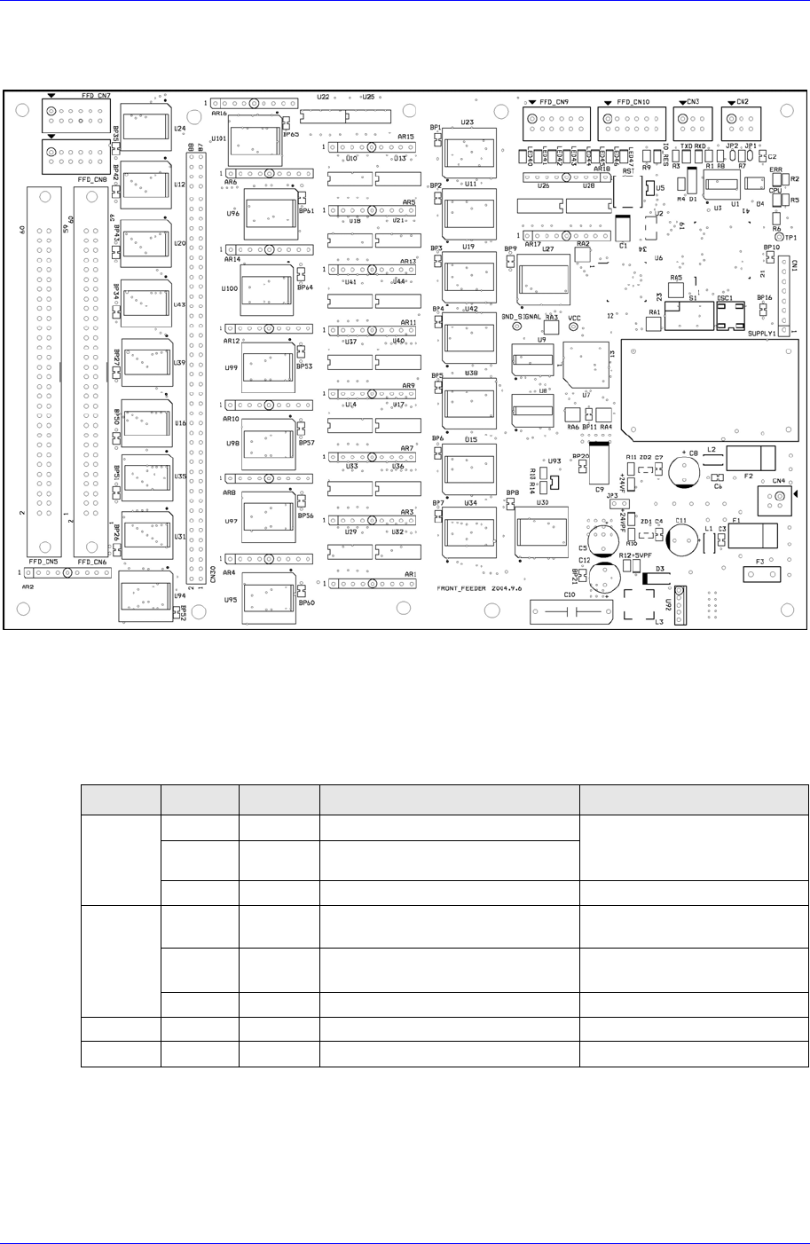
7.3.4. Feeder Control Board
Receives commands from the CAN Master Board to operate the feeder solenoid valve.
Required power supply
External power input: +24V DC
Internal power required: +5V DC / +24V DC
Description of major functions
INPUT
PIN NO. DEF. DESCRIPTION REMARK
1 CANH CAN communication signal
2 CANL
Connection with CAN
communication signal of other
nodes
CN2/CN3
3 /IO-RES RESET Signal FROM CAN MASTER
1 24VP DC+24V for OUTPUT PORT
Apply after inputting the READY
SW
2 24V DC+24V for INPUT PORT
then DC+5V for BOARD is
generated
CN4
3/4 24G DC+24V GROUND -
CN9 1~12 IN1.0~1.3 RESERVED INPUT PORT -
CN10 1~12 IN1.4~1.7 RESERVED INPUT PORT -
Samsung Component Placer CP45NEO Series Maintenance Guide
OUTPUT
PIN NO. DEF. DESCRIPTION REMARK
1~16 OUT1.0~1.7 FEEDER SOL #1~#8
17~32 OUT2.0~2.7 FEEDER SOL #9~#16
33~48 OUT3.0~3.7 FEEDER SOL #17~#24
CN5
49~56 OUT4.0~4.3 FEEDER SOL #25~#28
PIN 57~60 : N.C.
1~8 OUT4.4~4.7 FEEDER SOL #29~#32
9~24 OUT5.0~5.7 FEEDER SOL #33~#40
25~40 OUT6.0~6.7 FEEDER SOL #41~#48
CN6
41~56 OUT7.0~7.7 FEEDER SOL #49~#56
PIN 57~60 : N.C.
FEEDER SOL #53~#56
: NOT USED
CN7 1~12 OUT8.0~8.3 RESERVED OUTPUT PORT -
CN8 1~12 OUT8.4~8.7 RESERVED OUTPUT PORT -
LED information for board status diagnosis
LED ON DESCRIPTION REMARK LED ON DESCRIPTION REMARK
LED1 Can transmission TXD LED5 IO RESET
IORES
LED2 Error Occurrence ERROR LED6 Board Output Power
+24VPF
LED3 Receiving Can RXD LED7 Board Operation Power
+24VF
LED4 CPU Operation CPU LED40 Feeder Cart In
INPUT
7-18
Inspection of the Controller
7-19
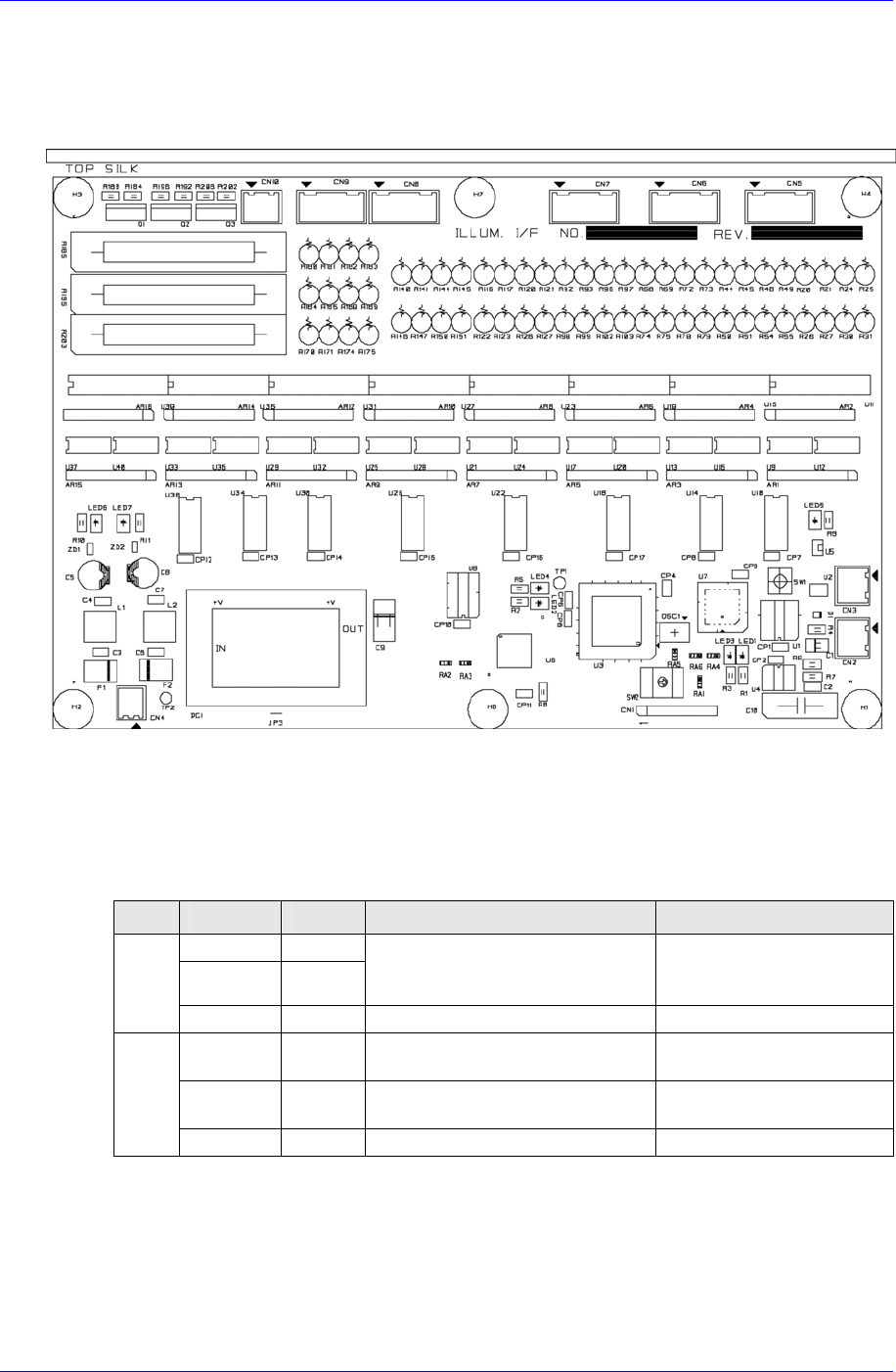
7.3.5. Illumination Control Board – Flying / Stage Camera
Receives commands from the CAN Master Board to adjust the brightness of the lighting
for the flying camera and stage camera. (Head Illumination I/F Board, Stage Illumination
I/F Board)
Required power supply
External power input: +24V DC
Internal power required: +5V DC / +24V DC
Description of major functions
INPUT
PIN NO. DEF. DESCRIPTION REMARK
1 CANH
2 CANL
CAN communication signal
Connection with CAN
communication signal of other
nodes
CN2/
CN3
3 /IO-RES RESET Signal FROM CAN MASTER
1 24VP DC+24V for OUTPUT PORT
Apply after inputting the
READY SW
2 24V DC+24V for INPUT PORT
Then DC+5V for BOARD is
generated
CN4
3/4 24G DC+24V GROUND -