CP45FVNEO Maintenance Reference (Eng, Ver3).pdf - 第128页
Samsung Component Placer CP45NEO Series Maintenance Guide OUTPUT PIN NO. DEF. DESCRIPTION REMARK 1/2 +24VPF Power For LED BOARD 3/4 OUT1.0~1.3 HEAD#1 FRONT(STAGE#1 FRONT) Illumination 5/6 +24VPF Power For LED BOARD 7/8…
Inspection of the Controller
7-19
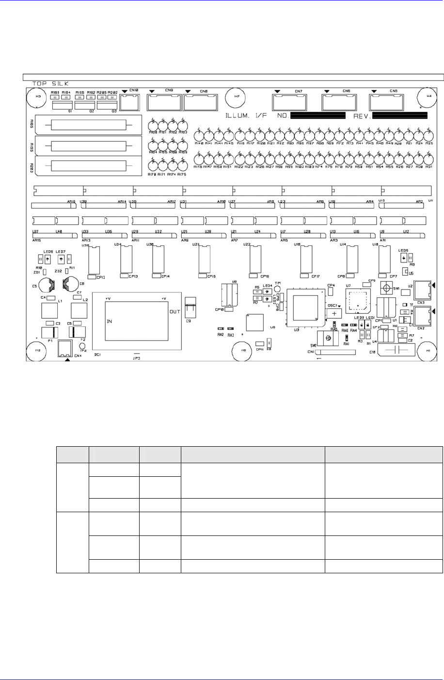
7.3.5. Illumination Control Board – Flying / Stage Camera
Receives commands from the CAN Master Board to adjust the brightness of the lighting
for the flying camera and stage camera. (Head Illumination I/F Board, Stage Illumination
I/F Board)
Required power supply
External power input: +24V DC
Internal power required: +5V DC / +24V DC
Description of major functions
INPUT
PIN NO. DEF. DESCRIPTION REMARK
1 CANH
2 CANL
CAN communication signal
Connection with CAN
communication signal of other
nodes
CN2/
CN3
3 /IO-RES RESET Signal FROM CAN MASTER
1 24VP DC+24V for OUTPUT PORT
Apply after inputting the
READY SW
2 24V DC+24V for INPUT PORT
Then DC+5V for BOARD is
generated
CN4
3/4 24G DC+24V GROUND -
Samsung Component Placer CP45NEO Series Maintenance Guide
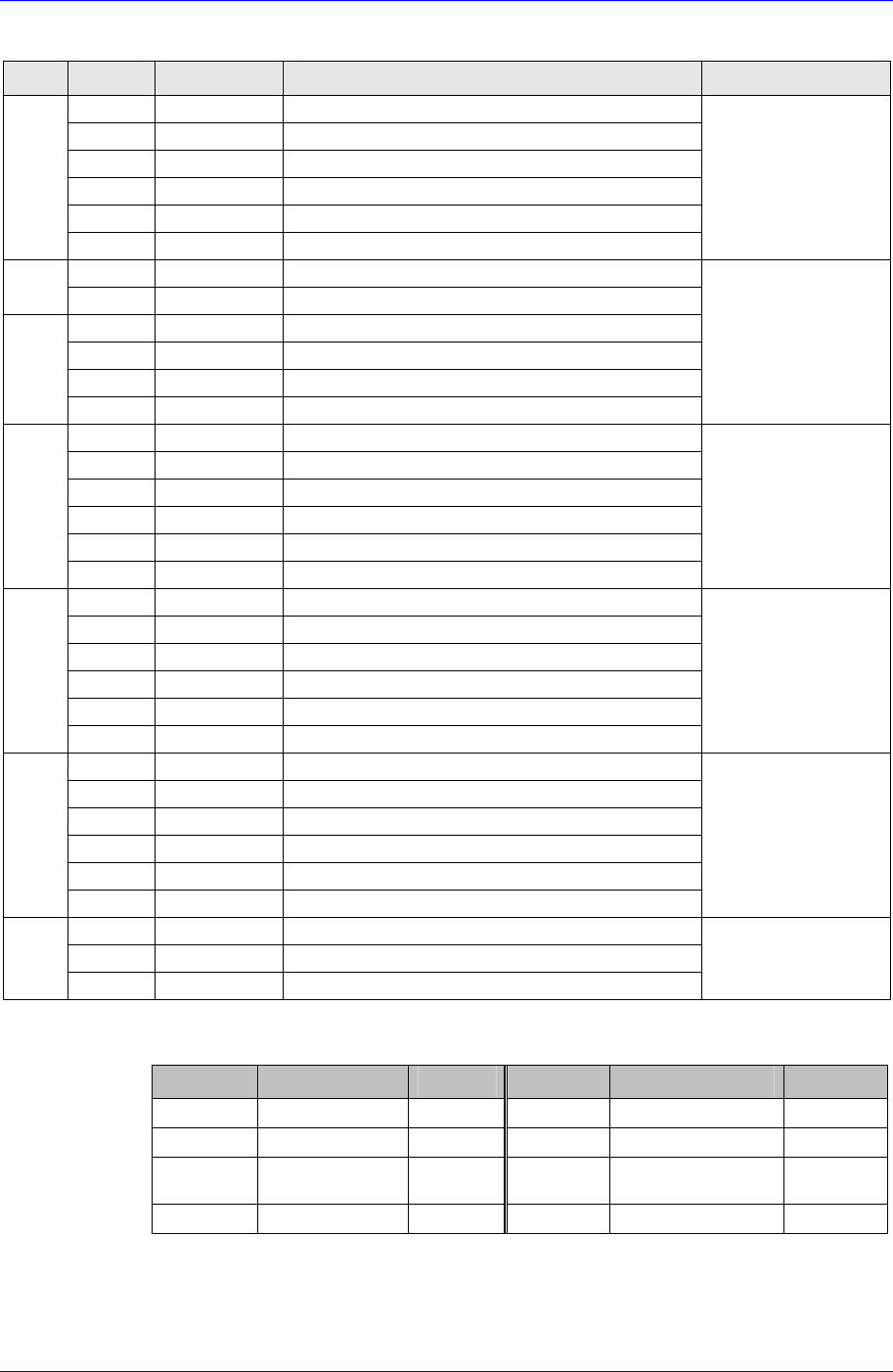
OUTPUT
PIN NO. DEF. DESCRIPTION REMARK
1/2 +24VPF Power For LED BOARD
3/4 OUT1.0~1.3
HEAD#1 FRONT(STAGE#1 FRONT)
Illumination
5/6 +24VPF Power For LED BOARD
7/8 OUT1.4~1.7
HEAD#2 FRONT(STAGE#1 UPPER)
Illumination
9/10 +24VPF Power For LED BOARD
CN5
11/12 OUT2.0~2.3
HEAD#3 FRONT(STAGE#1 SIDE)
Illumination
12PIN CONNECTOR
1/2 +24VPF Power For LED BOARD
CN6
3/4 OUT2.4~2.7
HEAD#4 FRONT(STAGE#2 FRONT)
Illumination
5/6 +24VPF Power For LED BOARD
7/8 OUT3.0~3.3
HEAD#5 FRONT(STAGE#2 UPPER)
Illumination
9/10 +24VPF Power For LED BOARD
CN6
11/12 OUT3.4~3.7
HEAD#6 FRONT(STAGE#2 SIDE)
Illumination
12PIN CONNECTOR
1/2 +24VPF Power For LED BOARD
3/4 OUT4.0~4.3
HEAD#1 SIDE(STAGE#3 FRONT)
Illumination
5/6 +24VPF Power For LED BOARD
7/8 OUT4.4~4.7
HEAD#2 SIDE(STAGE#3 UPPER)
Illumination
9/10 +24VPF Power For LED BOARD
CN7
11/12 OUT5.0~5.3
HEAD#3 SIDE(STAGE#3 SIDE)
Illumination
12PIN CONNECTOR
1/2 +24VPF Power For LED BOARD
3/4 OUT5.4~5.7
HEAD#1 DIFFUSE(STAGE#4 FRONT)
Illumination
5/6 +24VPF Power For LED BOARD
7/8 OUT6.0~6.3
HEAD#2 DIFFUSE(STAGE#4 UPPER)
Illumination
9/10 +24VPF Power For LED BOARD
CN8
11/12 OUT6.4~6.7
HEAD#3 DIFFUSE(STAGE#4 SIDE)
Illumination
12PIN CONNECTOR
1/2 +24VPF Power For LED BOARD
3/4 OUT7.0~7.3
HEAD#4 DIFFUSE(STAGE#5 FRONT)
Illumination
5/6 +24VPF Power For LED BOARD
7/8 OUT7.4~7.7
HEAD#5 DIFFUSE(STAGE#5 UPPER)
Illumination
9/10 +24VPF Power For LED BOARD
CN9
11/12 OUT8.0~8.3
HEAD#6 DIFFUSE(STAGE#5 SIDE)
Illumination
12PIN CONNECTOR
1 OUT8.4
BACK
Illumination
3 OUT8.5
BACK
Illumination
CN10
5 OUT8.6
BACK
Illumination
6PIN CONNECTOR
LED information for board status diagnosis
LED ON DESCRIPTION REMARK LED ON DESCRIPTION REMARK
LED1 Can transmission LED5 IO RESET
LED2 Error Occurrence LED6 Board Output Power
LED3 Can Receiving LED7
Board Operation
Power
LED4 CPU Operation
7-20

Inspection of the Controller
7-21
7.4. Inspection of the Motor Part
Check following items.
7.4.1. X-axis
Check if the power of the motor drive is normal. Initially, ‘r 0’ is indicated on the
LED display window. (This means the current RPM of the motor is 0.)
Check to see if the command connector from the axis board is connected properly.
Check the status of encoder line and power supply line.
Check the connector terminal status and connection status of each drive.
Move the head manually and check the change of motor RPM in the LED Display
with the machine remaining in READY-OFF state.
At this time, change the direction of movement manually and check if the sign of the
RPM shown in the LED Display is changed
7.4.2. Y-axis
Check if the power of the motor drive is normal. Initially, ‘r 0’ is indicated on the
LED display window. (This means the current RPM of the motor is 0.)
Check to see if the command connector from the axis board is connected properly.
Check the status of encoder line and power supply line.
Check the connector terminal status and connection status of each drive.
Move the X-Frame manually and check the change of motor RPM in the LED
Display with the machine remaining in READY-OFF state.
At this time, change the direction of movement manually and check if the sign of the
RPM shown in the LED Display is changed.
7.4.3. Z1~Z6, S, W axis
Check if the power of the motor drive is normal. Initially, ‘r 0’ is indicated on the
LED display window. (This means the current RPM of the motor is 0.)
Check to see if the command connector from the axis board is connected properly.
Check the status of encoder line and power supply line.
Check the connector terminal status and connection status of each drive
Move the head manually and check the change of motor RPM in the LED Display
with the machine remaining in READY-OFF state.
At this time, change the direction of movement manually and check if the sign of the
RPM shown in the LED Display is changed.
7.4.4. R1/2, R3/4, R5/6 axis (THETA1, THETA2, THETA3)
Check the power of the motor drive.
Check to see if the command connector from the axis board is connected properly.
The command connector is connected to the CN2, CN5, CN8 of the STEP I/F board.
Check to see if the R1/2(THETA1), R3/4(THETA2), R5/6(THETA3) from the CN3,
CN6, CN9 of the STEP I/F board is connected properly.