CP45FVNEO Maintenance Reference (Eng, Ver3).pdf - 第66页
Samsung Component Placer CP45NEO Series Maintenance Refer ence Sensor W indow Sensitivity Control Screw Red LED Green LED Lightness/Darkness Adjusting Screw If any problems still occur , contact our designated C/S comp…
Weekly Inspection
3-15
Warning
After clicking the “Motor Free” button on the teaching box,
click the “Stop” button on the front operation panel.
Conduct inspection while the motor power supply is turned
off.
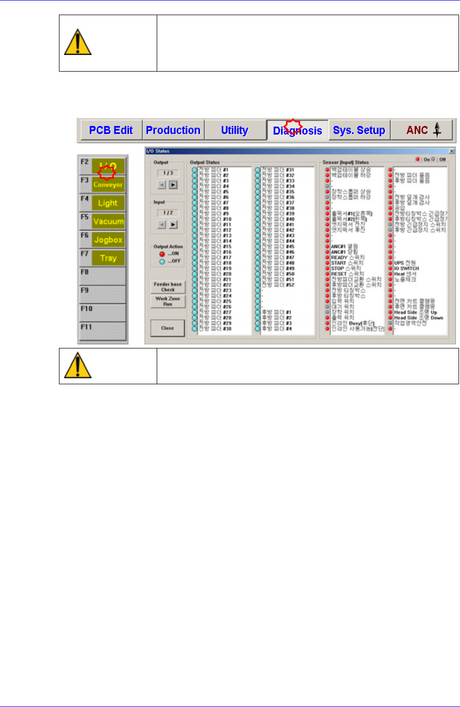
After selecting the Diagnosis from the main menu tool bar in the MMI screen, select
the I/O command from the sub menu tool bar to check the sensor operation.
Warning
Do not insert any part of your body into the machine during
I/O testing. Otherwise, serious injury may result.
After checking the quality of recognition, clean the sensor window using the swab
and clean cloth included in the cleaning kit provided by us.
Check the state of the cable connector assembly connecting with the sensor.
Check the sensitivity of sensor.
The conditions for detection may vary depending on the installation method, distance,
and angle and location of each sensor as well as due to dust, external light, shape, and
color of the board. Therefore, sensitivity of a sensor should be adjusted by using the
actual board that will be used. When adjusting the sensitivity of the board detecting
sensor, if there is no PCB, neither the red nor the green LEDs shall be turned on. The
“lightness/darkness“ adjusting screw shall always be turned to the “L” side.
If there is a PCB, turn the sensitivity adjusting screw clockwise so that both the red
and green LEDs are turned on.
If the “lightness/darkness“ adjusting screw is not turned to the “L” side, only the red
LED is turned on.
For reference, the sensitivity of the input sensor, quick load sensor and output sensor
cannot be adjusted.
Samsung Component Placer CP45NEO Series Maintenance Reference
Sensor Window
Sensitivity Control Screw
Red LED
Green LED
Lightness/Darkness Adjusting Screw
If any problems still occur, contact our designated C/S company (STS) and local
agent.
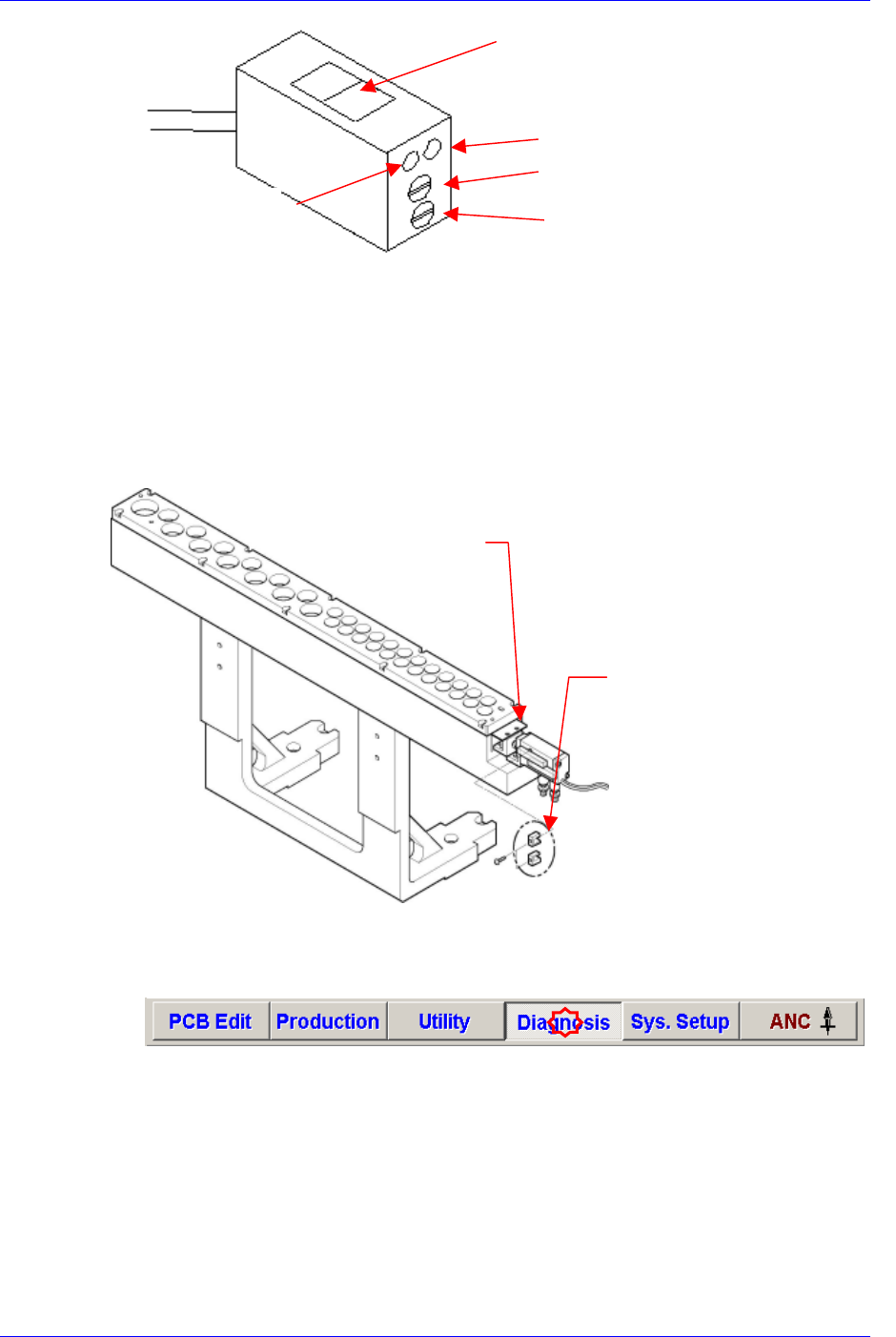
3.1.6. ANC Open/Close Sensor
Inspection
To determine the accurateness of the open/close action of the ANC shutter, check the
sensor operation through the MMI monitor.
Solution
ANC Shutte
r
ANC Open/Close
Sensor
After selecting the Diagnosis from the main menu tool bar in the MMI screen, select
the I/O command from the sub menu tool bar to check the sensor operation.
3-16
Weekly Inspection
3-17
Warning
Do not insert any part of your body into the machine during
I/O testing. Otherwise, serious injury may result.
If any problems still occur, contact our designated C/S company (STS) and local
agent.
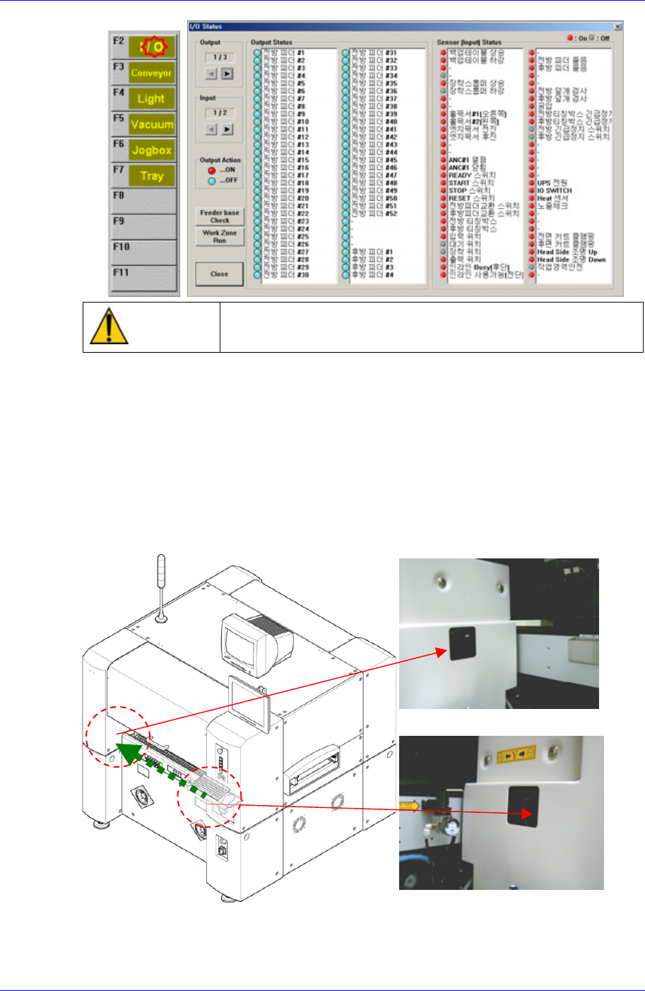
3.1.7. Feeder Unlock Sensor
점검
Feeder unlock sensors are installed at the front and rear of this machine. The system
comes into the emergency stop status if the feeder is not installed correctly at the feeder
base. In this case, verify that the feeder is installed properly.
Front Feeder Unlock Sensor (Ligh
t
receiving section)
Front Feeder Unlock Sensor (Ligh
t
emitting section)