CP45FVNEO Maintenance Reference (Eng, Ver3).pdf - 第81页
W eekly Inspection 3-31 3.2.5. Feeder S tation Cylinder Inspection Check the Feeder Station Cylinder . In case the operation of the cylinder is not s mooth, picking up of the parts may also not be smooth. Solution Feeder…
Samsung Component Placer CP45NEO Series Maintenance Reference
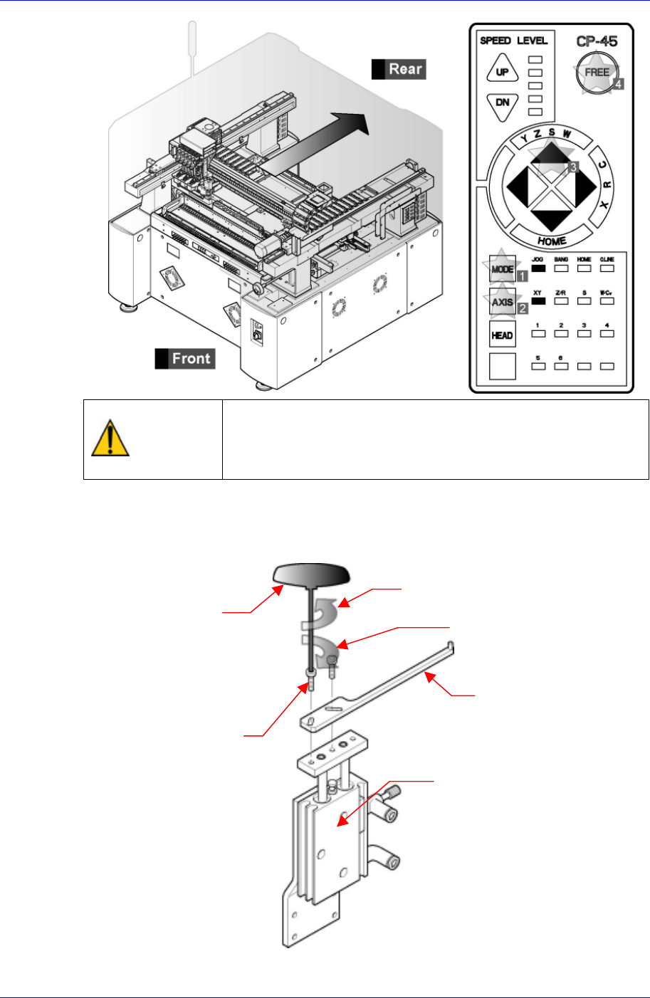
Warning
After clicking the “Motor Free” button on the teaching box,
click the “Stop” button on the front operation panel.
Conduct inspection while the motor power supply is turned
off.
For replacement, remove the bolt (M3*L10) connecting the conveyor PCB stopper
cylinder and stopper upper plate using a T-wrench (2.5mm) among the tools provided
by us, and replace the stopper top plate with a new one.
Separation direction (counterclockwise)
T wrench (2.5mm)
Assembly direction (clockwise)
Stopper Upper Plate
Bolt(M3*L10)
CONV PCB Stopper Cylinder
Assembling is done in the reverse order.
3-30
Weekly Inspection
3-31
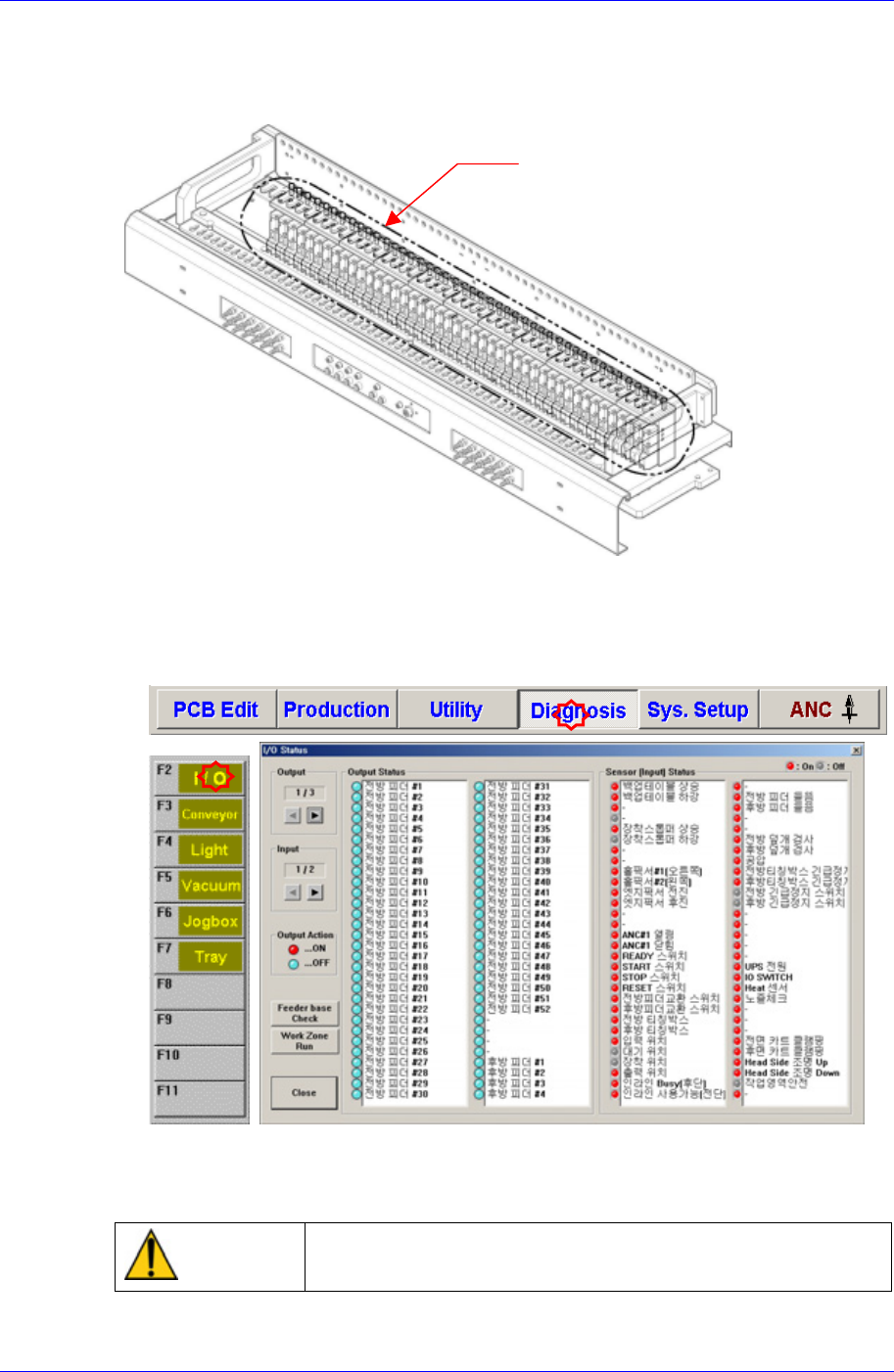
3.2.5. Feeder Station Cylinder Inspection
Check the Feeder Station Cylinder. In case the operation of the cylinder is not smooth,
picking up of the parts may also not be smooth.
Solution
Feeder Station Cylinder Ass’y
Remove all the feeders installed in the feeder station
After selecting the Diagnosis from the main menu tool bar in the MMI screen, select
the I/O command from the sub menu tool bar to check the sensor operation.
Operate sequentially from the No. 1 cylinder of the front feeder station.
In case the operation of the cylinder is not smooth, please contact our customer
satisfaction company (STS) or local agent.
Warning
Do not insert any part of your body into the machine during
I/O testing. Otherwise, serious injury may result.
Samsung Component Placer CP45NEO Series Maintenance Reference
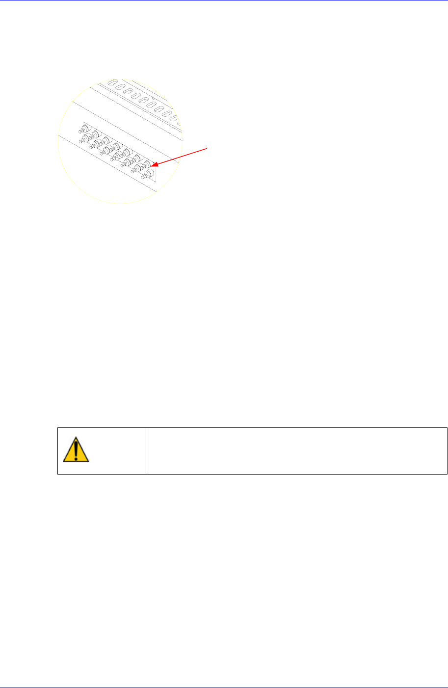
3.2.6. Adjustment of Multi Cylinder Speed
Inspection
Check if the working speed of the cylinder driving the tape feeder causes any
problem in relation to the placement of the components.
Figure 3-7. Speed Control Valve
Solution
Speed Control Valve
Adjust using the speed control valve for the multi-cylinders.
3.2.7. Air Filter & Auto Drainer
Inspection
Check ff the pneumatic pressure of the machine is normal with the air pressure gauge
of the air panel on the front side of the machine. (If the air filter is clogged, the air
pressure becomes low).
Check if there is accumulated water in the air filter of the air panel on the rear side of
the machine.
Visually check through the acryl cover if the color of the filter element is change.
Visually check if the water is drained well from the drainer.
If the tube is not inserted in the drainer, insert it
Warning
If the air filter or filter element is replaced without shutting off
the air supply line, personal injury may occur. Shut off the air
supply line before replacing the air filter or filter element.
Solution
Shut off the pneumatic air supplied to the machine from the air line.
The message that the pneumatic pressure is low in the machine is displayed in the
MMI dialog box with the yellow lamp (or blue lamp) of the signal light turned on. (If
the pneumatic pressure is supplied after replacement is completed, the machine turns
to normal state).
Through the inspection window of the air filter on the air panel cover at the right side
seen from the rear of the machine, check visually if the color of the filter element in
the air filter has been changed.
3-32