00197569-01_MM_DLM34_Kunde_en.pdf - 第21页
Minor Maintenance 3.1.4 Performing Maintenance Tasks Maintenance Tasks for DLM Maintenance Manual SIPLACE Placement Heads DL M3/DLM4 21 Application ► After cleaning the valve plunger, hold it tight with your fingers and …
Minor Maintenance
Maintenance Tasks for DLM 3.1.4 Performing Maintenance Tasks
20 Maintenance Manual SIPLACE Placement Heads DLM3/DLM4
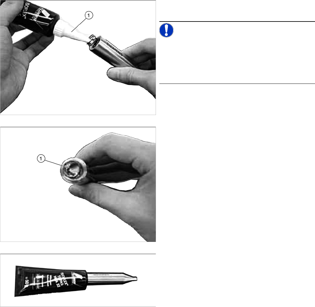
► Fill the cylinder with ISOFLEX TOPAS NCA 52, using
the adapter (1) provided with the TOPAS.
NOTICE!
This tool works best without air in the cylinder.
Make sure that, where possible, no air gets into the cylin
-
der.
Any air or ISOFLEX TOPAS NCA 52 in the cylinder could
impair the lubrication quality.
1. ISOFLEX TOPAS NCA 52
The diagram shows the state after filling the cylinder
with ISOFLEX TOPAS NCA 52.
► Take the adapter off the TOPAS tube, press the air
out of the TOPAS tube and attach the cylinder with a
rotary movement.
Minor Maintenance
3.1.4 Performing Maintenance Tasks Maintenance Tasks for DLM
Maintenance Manual SIPLACE Placement Heads DLM3/DLM4 21
Application
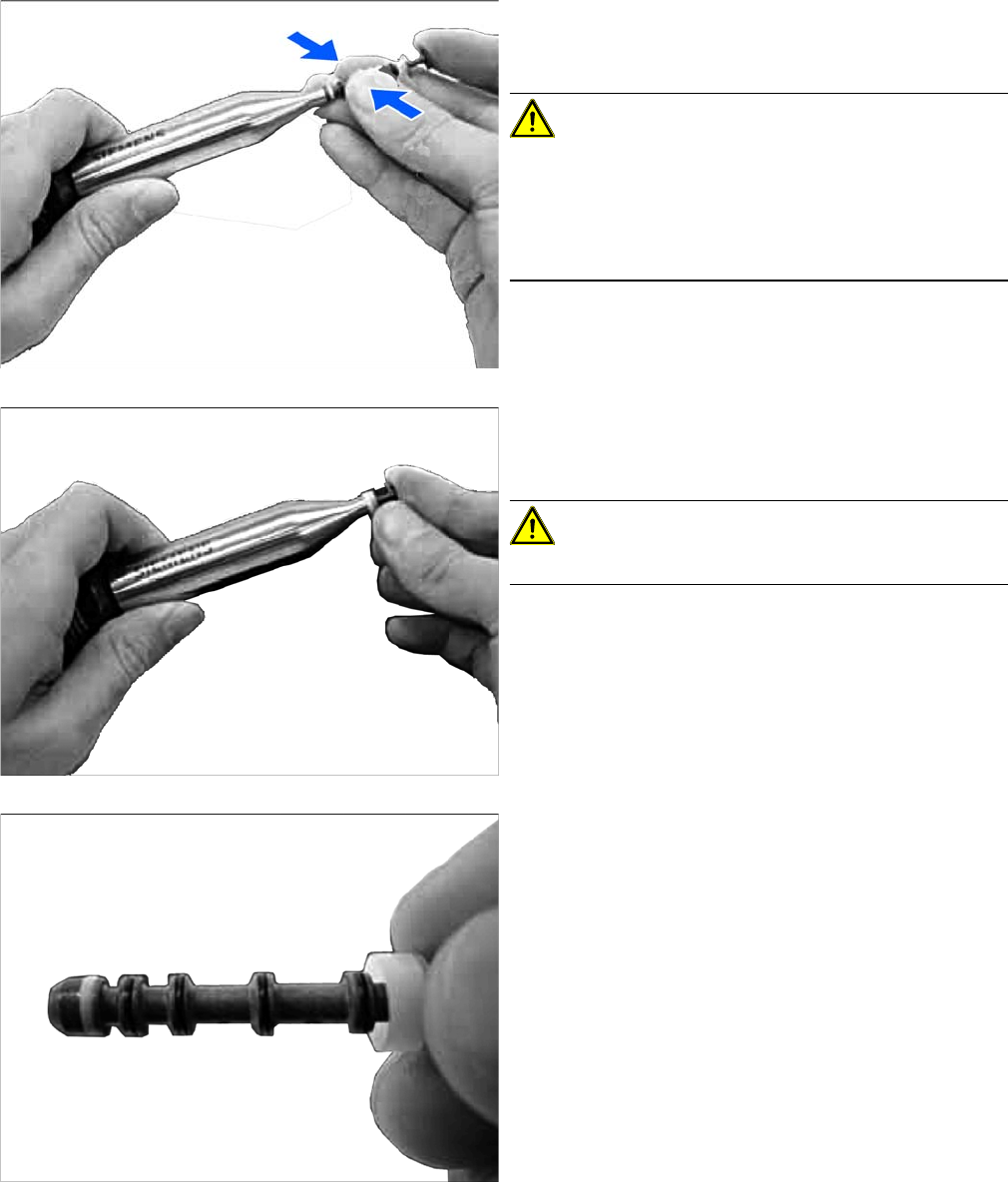
► After cleaning the valve plunger, hold it tight with your
fingers and insert it into the cylinder, making sure that
you hold it straight during insertion.
CAUTION!
When you insert the valve plunger, you will feel the resist
-
ance of the tool spring. Hold the valve plunger on the
sides with your fingers to support it.
If you do not support the valve plunger on the sides, this
could be bent and might break!
► Push the valve plunger once up to the end of the cyl
-
inder (full stroke) and then push it four or five times in
and out (10 to 15 mm stroke).
CAUTION!
Make sure that there is enough grease on the tool!
► Take out the valve plunger and check the result on
the outside of the O-ring surface. If the surface of the
O-ring shines with TOPAS, the valve plunger has
been properly greased.
Minor Maintenance
Maintenance Tasks for DLM 3.1.4 Performing Maintenance Tasks
22 Maintenance Manual SIPLACE Placement Heads DLM3/DLM4
3.1.4.5
3.1.4.5 Inserting the Valve Plungers
Inserting the Valve Plungers
3.1.4.6
3.1.4.6 Replacing the Sleeves
Replacing the Sleeves
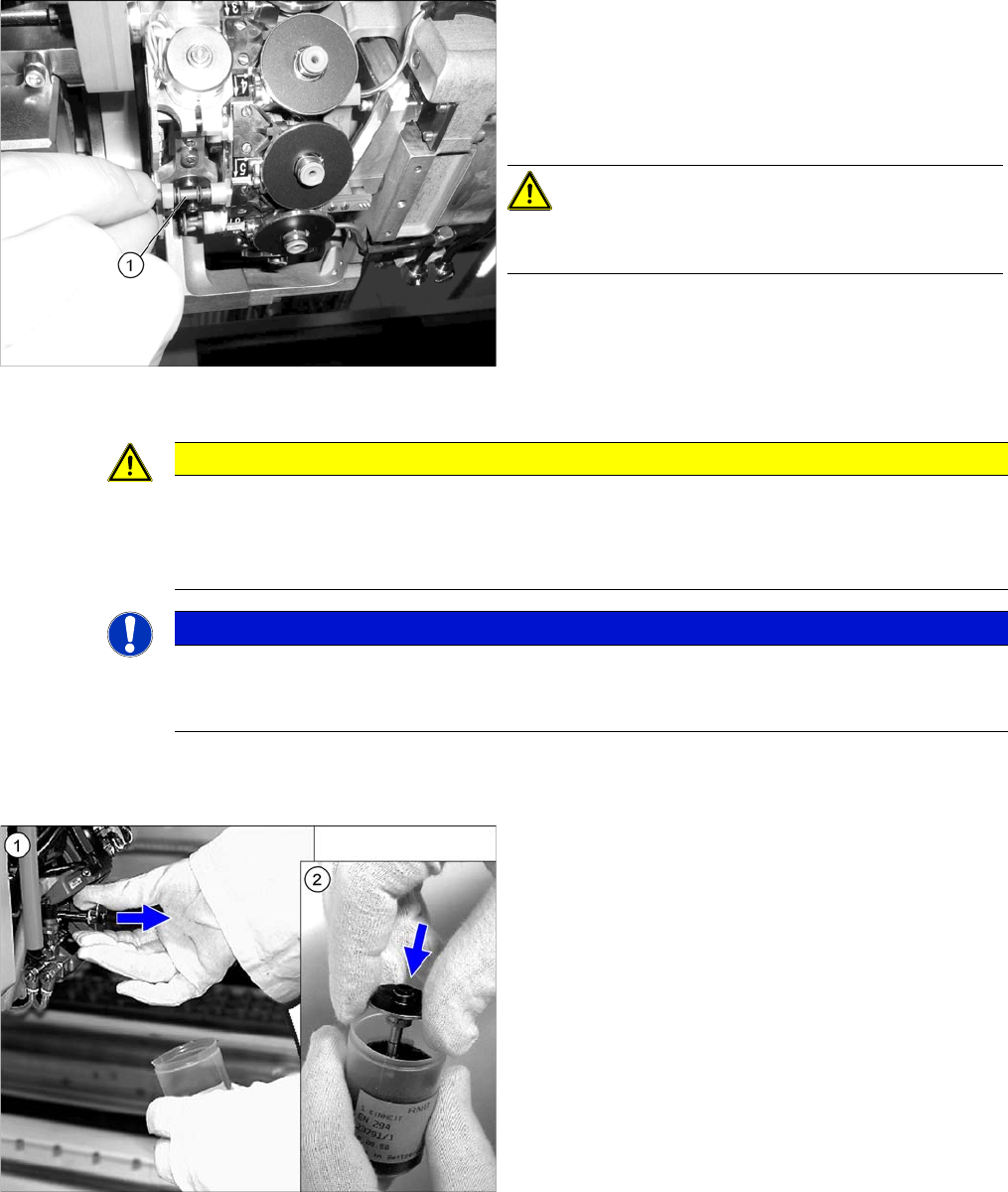
► Set the placement head nozzles down in the nozzle changer.
► Open the Safety Cover.
► Insert cleaned of if necessary, new valve
plungers (1).
Grease the valve plungers before inserting them
(see section "3.1.4.4 Greasing the Valve Plungers"
[ ➙ 19]). If they move too easily or are stiff to move,
replace the valve plungers.
CAUTION!
Make sure that the valve plungers are inserted as far as
the stop.
CAUTION
Laboratory gloves
► Do not hold the sleeves in your bare hands. Wear protective gloves when performing main
-
tenance tasks to the sleeve. This helps to avoid unnecessary contamination of the glass or
friction wheel. This contamination could lead to malfunctions (counting errors or overswing).
NOTICE
Sleeves
We recommend that you have a cleaned set of sleeves ready, in case you need to replace con
-
taminated ones.
► (1) Pull the sleeve out of the head.
► (2) Place the sleeves in the vessel provided.
► Turn the star on to the next segment.
► Repeat these steps for all segments, until all sleeves
have been removed.
► Insert the cleaned sleeves into the segments. Use a
very gentle pressure to engage the sleeves to avoid
damaging the retaining springs.