00197569-01_MM_DLM34_Kunde_en.pdf - 第47页
Major Maintenance 4.1.4 Performing Maintenance Tasks Maintenance Tasks for DLM Maintenance Manual SIPLACE Placement Heads DL M3/DLM4 47 4.1.4.9 4 . 1 . 4 . 9 C o m p o n e n t s e n s o r ( o n ly D L M 3 ) Component sen…
Major Maintenance
Maintenance Tasks for DLM 4.1.4 Performing Maintenance Tasks
46 Maintenance Manual SIPLACE Placement Heads DLM3/DLM4
► Fit the vacuum generator and silencer. Follow the removal instructions in reverse order for installa
-
tion. Also observe the following instructions:
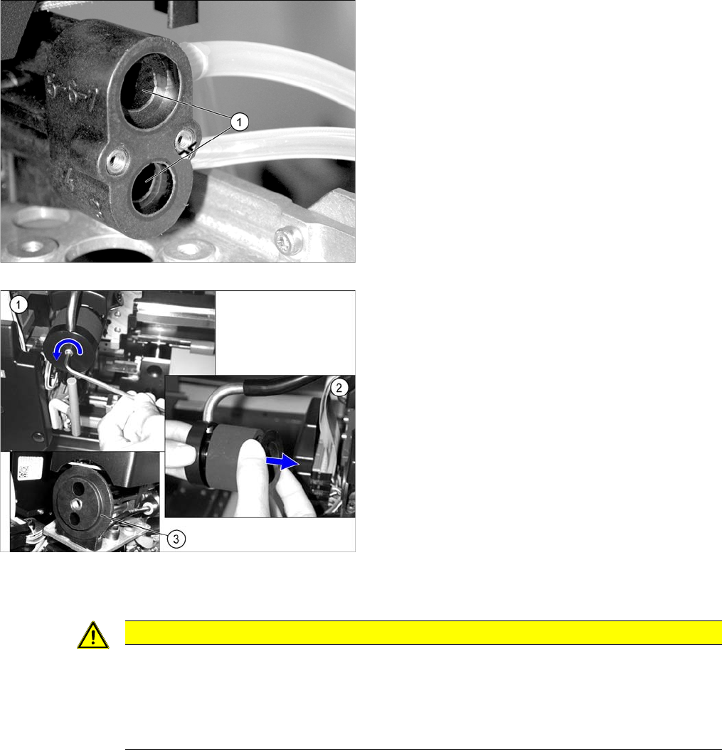
► Clean the drilled holes (1) to the vacuum nozzles with
a cleaning stick moistened with ethanol.
Check or replace the silencer on the vacuum generator.
► (1) Loosen the screw used to fix the C&P head silenc
-
er.
► (2) Check the silencer for dirt. If the silencer shows
discoloration, remove it and replace it with a new one.
► Clean the O-ring (3) [00343022-xx] with a dry lint-free
cloth and then grease slightly with UNISILKON
L250L. If the O-ring is damaged, replace it.
► Check the plastic fixture for the silencer for cracks or
other damage. If the fixture is damaged, the silencer
has to be replaced by authorized personnel. For re
-
moval and installation details, read the Service man
-
ual.
CAUTION
Installation instructions
► Carefully screw the vacuum generator block with the vacuum nozzles tight.
► Before the Venturi nozzles are refitted with the O-rings, make sure that the ethanol has
evaporated completely. If this is not the case, the O-rings could be dissolved over time by
the ethanol.
Major Maintenance
4.1.4 Performing Maintenance Tasks Maintenance Tasks for DLM
Maintenance Manual SIPLACE Placement Heads DLM3/DLM4 47
4.1.4.9
4.1.4.9 Component sensor (only DLM3)
Component sensor (only DLM3)
CAUTION
Prisms, cleaning sticks
► Take care not to damage the component sensor prisms.
► Make sure that you do not use the cleaning sticks soaked in oil from cleaning the sleeves.
Always use a new cleaning stick!
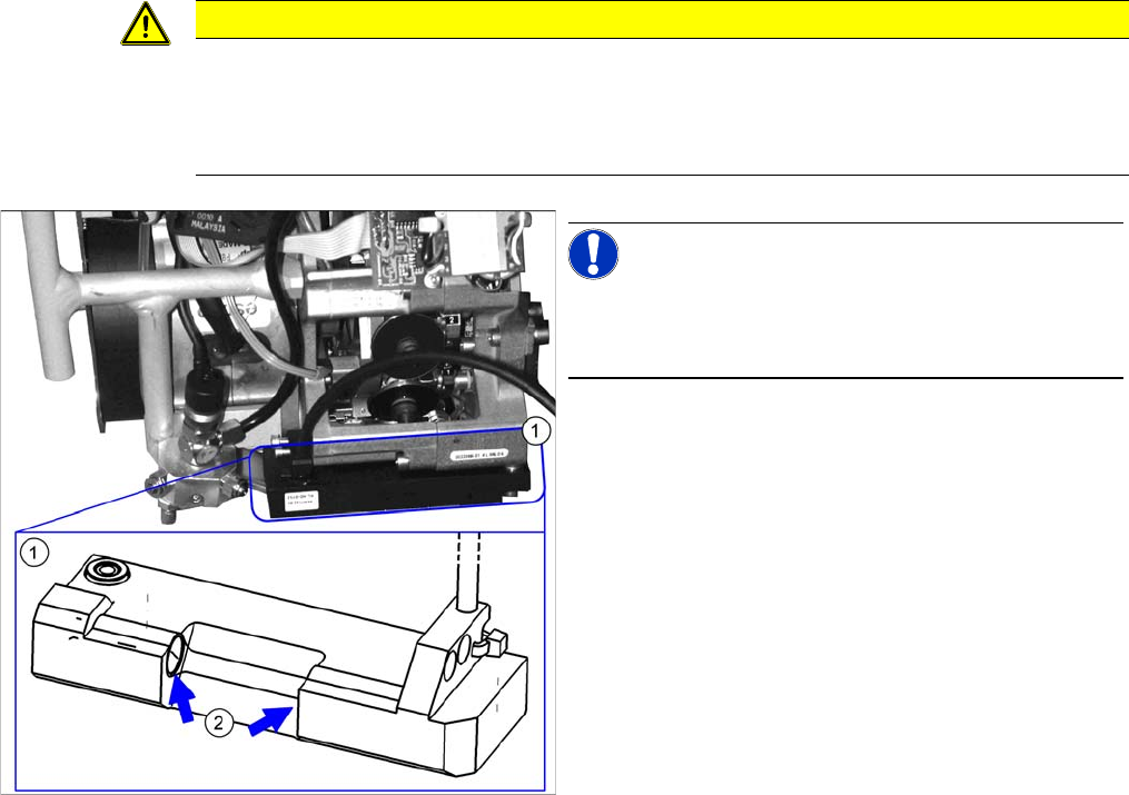
NOTICE!
For clarity, the diagram shows the component sensor
when removed from the machine. However, you do not
need to remove it when cleaning the component sensor.
► Clean the prisms (2)on the rear side of the compo
-
nent sensor (1) with a cleaning stick soaked in etha
-
nol.

Major Maintenance
Maintenance Tasks for DLM 4.1.5 Final Work
48 Maintenance Manual SIPLACE Placement Heads DLM3/DLM4
4.1.5
4.1.5 Final Work
Final Work
Fitting the front section of the head
For details, refer to the service manual.
► Insert the two O-rings into the back part of head.
► Carefully insert the distributor into its seat.
► Turn the placement star half a step (C&P6: 30°, C&P12: 15°), fit the front part of the head and screw
tight.
► Reconnect the system to the electrical and compressed air systems.
► Insert cleaned or new sleeves into the segments.
► Insert cleaned or new valve plungers into the valve housing.
Fitting the Placement Head
► Fit the placement head back onto the gantry. Read the service manual for your machine first.
► Switch the placement machine on at the main switch.
► Let the placement head take up the nozzles again.
Test placement:
► The distance between the component camera and the PCB camera can be changed by separating
the front and back parts of the head.
► Carry out a test placement run to test whether the placement accuracy is still guaranteed.
► If the placement accuracy is not guaranteed, calibrate the segment offset 2.
CAUTION
Damage to the O-rings
The O-rings must not be seated on the distributor, otherwise they may be damaged.
► Insert the O-rings into the back part of head.