00197569-01_MM_DLM34_Kunde_en.pdf - 第9页
Introduction 1.3.1 Environmentally-Friendly Di sposal of Materials and Compon ents Other Instructions Maintenance Manual SIPLACE Placement Heads DL M3/DLM4 9 1.3 1 . 3 O t h e r I n s t r u c t io n s Other Instructions …
Introduction
Maintenance Notes 1.2.2 Calculation of Maintenance Intervals
8 Maintenance Manual SIPLACE Placement Heads DLM3/DLM4
1.2.2
1.2.2 Calculation of Maintenance Intervals
Calculation of Maintenance Intervals
The SIPLACE maintenance intervals are time-based and set according to the following conditions:
▪ Shift model: eight hours per shift, three shifts per day, five days a week and 50 weeks a year.
▪ Real placement performance in accordance with machine specifications
▪ Environmental and production conditions: see document "Conditions at Installation Site"
1.2.2.1
1.2.2.1 Adjusting the Maintenance Intervals to Actual Production Conditions
Adjusting the Maintenance Intervals to Actual Production Conditions
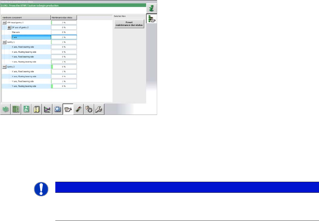
The maintenance status is calculated from the placement cycles, temperature and operating hours. The
status is shown as a progress bar (0 – 100 %).
Placement cycles for maintenance intervals:
▪ CPP: 40 mill. placed components
▪ C&P20: 30 mill. placed components
▪ C&P20A/M/P: 37.5 mill. placed components
Some customers want to adjust maintenance intervals to
their actual environment and production conditions. A
maintenance monitor can also be accessed in the station
software for some assemblies (from SW703.02).
The maintenance monitor is available for the following as
-
semblies:
▪CPP
▪ C&P20/A/M/P
▪ X and Y axis (SX1/SX2/DX1/DX2 only)
NOTICE
Maintenance counter
► After maintenance has been completed, the maintenance counter needs to be reset for the
assembly concerned.

Introduction
1.3.1 Environmentally-Friendly Disposal of Materials and Components Other Instructions
Maintenance Manual SIPLACE Placement Heads DLM3/DLM4 9
1.3
1.3 Other Instructions
Other Instructions
1.3.1
1.3.1 Environmentally-Friendly Disposal of Materials and Components
Environmentally-Friendly Disposal of Materials and Components
SIPLACE products are manufactured using only materials and parts that can be easily separated and
disposed of in an environmentally-friendly way.
1.3.2
1.3.2 Use of Original SIPLACE Accessories and Spare Parts
Use of Original SIPLACE Accessories and Spare Parts
Only use original spare parts and authorized accessories. The use of other parts will affect safety and
will invalidate the liability for any consequential damage.
1.3.3
1.3.3 ESD Guidelines
ESD Guidelines
1.3.3.1
1.3.3.1 Definition of ESD
Definition of ESD
1.3.3.2
1.3.3.2 Important Measures to Protect Against Static Charging
Important Measures to Protect Against Static Charging
► Most plastics can easily become charged and must therefore be kept away from at-risk components.
► Always ensure that people, the workplace and packaging are safely earthed when handling electro
-
static sensitive components.
NOTICE
Observe the applicable regulations
The company operating the system has sole responsibility for the proper, environmentally-
friendly disposal of machines, working materials, consumables and wear parts.
► Please observe your national statutory provisions for waste disposal and environmental
protection.
Almost all of the modules in use today are equipped with highly integrated MOS blocks and compo
-
nents. The manufacturing techniques used mean that these electronic components are extremely sen
-
sitive to overvoltage and thus to electrostatic discharge.
The abbreviation for such modules is 'ESD' (Electrostatic Sensitive Device). This is
used internationally, although the German abbreviation 'EGB' may also be seen. The
following symbol on cabinet rating plates, racks or packaging indicates that compo
-
nents which are sensitive to electrostatic discharge have been used and thus that the
modules concerned are also touch-sensitive.
ESDs can be destroyed by voltages and power levels that are far below the level that can be perceived
by humans. Such voltages occur if a person touches a component or module without earthing them
-
selves. Components that are exposed to such overvoltages do not generally appear to be defective im
-
mediately - incorrect behavior starts after the component or module has been in operation for some
time.
Introduction
Other Instructions 1.3.4 Validity of Document
10 Maintenance Manual SIPLACE Placement Heads DLM3/DLM4
1.3.3.3
1.3.3.3 Handling ESD Modules
Handling ESD Modules
Do not touch electronic modules unless it is absolutely essential to do so in order to carry out other work.
If it is necessary, make sure that you do not touch the pins or printed conductors when you pick up flat
modules.
Do not touch components unless
▪ You are constantly earthed by an ESD wrist strap or
▪ You are wearing ESD shoes or ESD shoe earthing strips on an ESD floor.
Always discharge yourself before you touch an electronic module. To do this, simply touch a conductive
and earthed object immediately before you touch the module (such as unpainted parts of a switch cab
-
inet, a water pipe, etc.).
Do not allow modules with chargeable and highly insulating materials to touch one another, e.g. plastic
films, insulating table surfaces or items of clothing made from synthetic fibers.
Always place the modules on a conductive surface (table with an ESD coating, conductive ESD foam,
ESD bag or container).
Do not bring modules near visual display units, monitors or televisions. Keep them at least 10 cm away
from the screen.
1.3.3.4
1.3.3.4 Measurements and Modifications to ESD Modules
Measurements and Modifications to ESD Modules
Measurements of the assemblies may only be taken if
▪ The measuring device has been grounded (e.g. via protective conductor) or
▪ The measuring head of the potential-free measuring device has been briefly discharged before
measurement (e.g. touching blank metal control unit housing).
► Always use an earthed soldering iron if you carry out any soldering work.
1.3.3.5
1.3.3.5 Dispatching ESD Modules
Dispatching ESD Modules
► Always store modules and components in conductive packaging (e.g. metallized plastic bags or met
-
al sleeves) and dispatch them in conductive packaging.
► If the packaging is not conductive, place the modules in a conductive envelope before packaging.
Use conductive foam rubber, ESD bags, domestic aluminum foil or paper, for example. NEVER use
plastic bags or film.
► If the module has integral batteries, ensure that the conductive packaging does not touch or short-
circuit the battery terminals and, if necessary, first cover the terminals with insulating tape or mate
-
rial.
1.3.4
1.3.4 Validity of Document
Validity of Document
This document contains maintenance work instructions for all SIPLACE placement heads of type DLM.
The work described in this manual is largely identical for all DLM types:
▪ If the work required should differ from the standard procedure, this will be indicated with reference
to the version and delivery state.
▪ Diagrams should be seen as examples e.g. the diagram of a SIPLACE DLM3 or a different paint fin
-
ish does not mean that the following information only applies to the type shown.