S25 circuit.pdf - 第17页
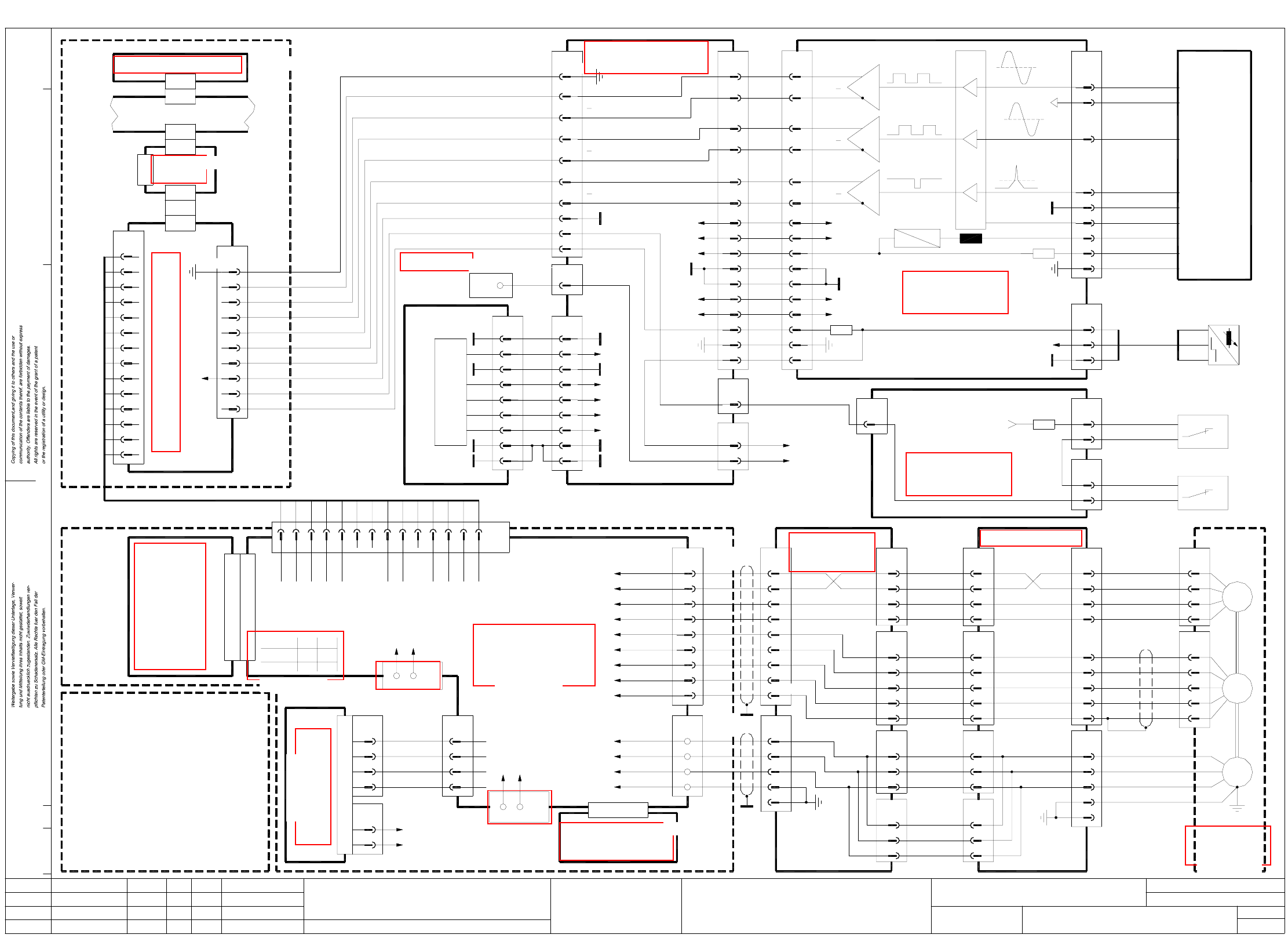
2 Detailed circuit diagrams 17 Y1-S25 Y -axis, gantry 1, SI PLACE S -25 HM 4 X12aa 1 +5V 00336690-xx (aa) Gantry conversion board Refer ence point End po sit ion prox. switch 1 X-axis ena ble for y 6 X35aa 2 003578 78-x …
2 Detailed circuit diagrams 16
X2-S25 X-axis, gantry 2, SIPLACE S-25 HM
S2S1
X11f
6
1
4z Tacho Mp
Nom+
12b
12z
to X34ba
Conversion board
gantry
RLG W
Tacho W
RLG U
30d,z,b Motor V
32d,z,b Motor U
GND
+Ub
-15V
signal
4
3
2
1
8
7
10
bk
bl
Tacho U
Tacho V
Tacho W
Tacho Mp
RSE V
RSE W
RSE +5V
RSE GND
Motor U
Motor V
Motor W
Power GND
RSE U
00343908-xx
3
4
5
10,11,12,13,14
X36ba
4
3
1
2
5
32
33
32
31
X37ba
29
30
33
X10ba
X11ba
30
32
33
X12bb
32
31
29
30
33
X2bb
3,6,9,12,15
4,7,10,13,16
2,5,8,11,14
3,6,9,12,15
4,7,10,13,16
X1bb
2,5,8,11,14
(cable)
00337532-xx
00321557-xx
(cable)
8
7
6
5
+5V
-15V
+15V
+5V
+24V
X19
2
3
4
X12ba
1
+5V
00336690-xx (ba)
Gantry conversion board
Reference point
End position
X-axis enable
Tacho U
Servo unit
00343723-xx
X1
00337333-xx A15
X5vm
6
X35ba
2
00357878-xx
Terminal strip
X2kf
2
(cable)
00344225-xx
wh
(lefthand side)
gantry 2
Distance sensor
00321557-xx
(cable)
00344206-xx A13 (vm)
13,2813,28
+5V
11
12
11
12
X10ba
24
X2bb
24
bl3 bl -
X16bc
1
2
(Cable)
00300609-xx
br
bk bk
br
+
A1
End pos. prox.
switch B1
+24V
X-axis,
axis tracks
X1sa
GND
X1vm
6
5
X8vm
1
2
3
4
X3vm
33
44
1
2
2
1
GND
Tacho-std
Ready
+15V
X11c
Anti-crash board
8b Enable input
Tacho std8d
Precontrol-14d
14b
Dynamic brake
DBM / 3P - 3
RSE
T
ye/gn
br
GND
Track B
3
4
2
1
Track A
X-axis incremental shaft encoder
X15bc
6
9
8
7
5
gnwh
bk
rd
bl
wh
br
ye
pk
gn
Zero pulse
Signal
(Track N)
Screen
LED
GND
+5V
LED
00300911-xx
(Cable)
8
9
27
26 Track N
Track N27
26
X3bc
00321554-xx
6
5
2
3
29
30
3.3k
33
32
X3ba
(Cable)
Track B
Track B29
30
Track A
Track A
33
32
X15ba
10
12
13
A
A
B
B
N
N
+15V
+5V
RI_TL
2525
2222
-15V
-15V
+15V
16
31
16
31
10
19
PGND
+24V
10
19
PGND
+24V
Gantry
00344486-xx (bc)
head distributor S23
X34ba
1
Control unit
Power supply
00356211-xx
00334520-xx
+24V
00344218-xx
(cable)
+5V
+15V
-15V
9
00336690-xx (ba)
Gantry
X8bb
3
1
wh
br
(Cable)
00321577-xx
Limit switch 1
X-axis
00321423-xx
End pos. prox. switches
B1, B2
Y-axis
00321425-xx
Limit switch 2
X-axis
00321578-xx
(Cable)
X9bb
3
1
wh
br
Conversion board
00336689-xx (bb)
large-axis
S1 S2
conversion board
X38ba
2
6
1
8
7
(cable)
X10ba
29
30
00321557-xx
00336689-xx (bb)
Conversion board
29
(cable)
X2bb
large-axis
wh
00321558-xx
(cable)
00337543-xx
00337542-xx
(cable)
A23 (vm)
X-axis (gantry 2)
+15V
-15V
2
1
X6vm
X7vm
1,2
3
-
0/155V
8
9
7
6
5
4
1
3
2
bl
br
ye
gr
rd
pk
gn
wh
(Gantry 2)
Axis
service
1,4,7,17,20
1,4,7,17,20
Screen
+5V
L2
+15V
+5V
1,341,34
00321571-xx
(cable)
Anti-crash board
to X11f/6
to X11f/1
1
Switch
Gantry 1
Gantry 2
2
12
AenderungZustand Datum
CAD-Datei : X2-S25.DWG
Urspr./Ers.f./Ers.d.NormName
Gepr.
Stromlaufplan/Circuit diagram
PL EA
Mat.-Nr. :
Beab. Hi
Datum 29.01.01
SIEMENS
SMD Placement System SIPLACE S-25 HM
1
1
X-axis, gantry 2
SIPLACE S-25 HM
U
V
W
X13bb
4
3
2
1
10
8
7
6
5
X3bb
5
4
3
2
1
5
4
3
2
XR
1
4
3
1
2
XT
Tacho U
Tacho V
Tacho W
Tacho Mp
RSE U
RSE V
RSE W
RSE +5V
RSE GND
U
V
W
M
3~
00337065-xx
S-23
ye
br
gn
ye/gn
ye
bk
rd
wh/bk
rd
vi
wh/br
or
X motor
(cable W2)
00337065-xx
(cable W1)
00337065-xx
Encoder
RSE = Rotary Shaft
prox. switch 1
End position
prox. switch 1
Sheet
Sh.
X2uc
Machine controller M54 A1 (sa)
X1 plug assignment / servo amplifier
+15V
Tacho V
Brake out
Precontrol+
Nom-
10z
12d
10b
10d
8z
Pos. stop
Ready
Neg. stop
4b
4d
6b
2d
2b
Motor W
Power GND
18z
18b
28d,z,b
26d,z,b
20d,z,b
RLG V
GND
+15V
I²t
Force
16z
18d
16b
14z
16d
A2 (vm)
00337625-xx
TBF 120 / 7 TS
X1
X-axis servo amplifier
X4vm
GND1
00356211-xx
Control unit
Cable 00344245-xx
rd
nom. values
X-axis
109
Axis rear panel, gantry 2 A29 (uc)
Ready out
8
GND
Enable3
2
Ready4
5I²t
6
7
14
12
13
10
11
12
13
11 Axis GND
Servo unit backplane
V nom9
10
Tacho-std12
GND
Force13
14
X2vm
00344256-xx
(Cable)
X1su
X1uc
7
8
5
6
00345015-xx
3
4
1
2
8
9
5
6
2
3
X5su
X1sm
A8 (tq)
SMP bus A32 (su)
Axis board
X24
X7uc
X2tq
X3tq
See page 65
See page 86
See page 132
See page 137
See page 131
See page 28
See page 65
See page 131
See page 132
See page 92
See page 79
See page 27
See page 73
See page 81
See page 80
See page 141
See page 74
2 Detailed circuit diagrams 17
Y1-S25 Y-axis, gantry 1, SIPLACE S-25 HM
4
X12aa
1
+5V
00336690-xx (aa)
Gantry conversion board
Reference point
End position
prox. switch 1
X-axis enable for y
6
X35aa
2
00357878-xx
Terminal strip
X2kf
1
(cable)
00344224-xx
wh
(lefthand side)
gantry 1
Crash signal
00321557-xx
(cable)
1,17,18,19,34
1,4,7,17,20
1,4,7,17,20
(Gantry 1)
service
Axis
8
9
7
6
5
4
1
3
2
bl
rd
pk
gr
ye
wh
gn
br
Power GND
Motor W
Motor V
Motor U
RSE GND
RSE +5V
Tacho Mp
Tacho W
Tacho V
Tacho U
00344206-xx A12 (vb)
DBM / 3P - 3
Dynamic brake
Precontrol-
Power GND
X1 plug assignment / servo amplifier
RLG U
Tacho W
Precontrol+
12z
12b
12d
RLG W
Tacho std
Enable input
Ready
Brake out
Tacho V
+15V8z
10d
10b
10z
8b
8d
6b
28d,z,b
32d,z,b
30d,z,b
Motor U
Motor V
18d
16z
20d,z,b
26d,z,b
18b
18z GND
+Ub
Motor W
-15V
+15V
GND
Y-axis servo amplifier
TBF 120 / 12 TS
00337626-xx
Nom+
Tacho Mp
Neg. stop
Pos. stop
Nom-
4b
4z
4d
2b
2d
14b
14d
16d
14z
16b
Force
I²t
RLG V
signal
Tacho U
00343723-xx
Servo unit
A6 (vb)
X1
00337333-xx A15
Anti-crash board
Ready33
Conversion board
X1
5
gantry
X11e
7
4
to X34aa
0/155V
+15V4
1,2
X7vb
-
3
X5vb
Gantry 1
Gantry 2
Switch
21
S1
1
S2
2
2
1
X11b
2
1
X6vb
-15V
+15V
X4vb
GND
Ready out
Enable
Ready
1
3
2
4
GND
I²t
Axis GND
V nom
8
5
6
7
9
10
11
Tacho-std
00343908-xx
Y-axis (gantry 1)
A19 (vb)
Servo unit backplane
Tacho-std2
1GND
X3vb
Force
GND
13
12
14
X2vb
W3br3
4 ye/gn 4
5
(cable W2)
00337066-xx
00337536-xx
X8vb
2
1
(cable)
bl
bk
RSE W 7
8
10
RSE U
RSE V
6
5
2
1
X31a
V
U
4
12
11
3
00337537-xx
X1vb
4
3
1
2
(cable)
10
2
X32a
1
9
rdV
Y motor S-23
00337066-xx
M
W
ye/gn
ye
3~
U
RSE GND
RSE +5V
RSE W
RSE V
RSE U
RSE
bk
vi
rd
2
4
XR
wh/br
wh/bk
or
5
3
1
Tacho Mp
Tacho W
Tacho V
Tacho U
XT
gn
br
wh
ye
4
3
T
1
2
to plug 11e
anti-crash board
6
13
00337066-xx
(cable W1)
(cable)
00321547-xx
Encoder
RSE = Rotary Shaft
Y-axis
End position
prox. switch 1
prox. switch 2
End position
Sheet
Sh.
AenderungZustand Datum
CAD-Datei : Y1-S25.DWG
Urspr./Ers.f./Ers.d.NormName
Gepr.
Stromlaufplan/Circuit diagram
PL EA
Mat.-Nr. :
Beab. Hi
Datum 29.01.01
SIEMENS
SMD Placement System SIPLACE S-25 HM
1
1
Y-axis, gantry 1
SIPLACE S-25 HM
X4sz
27
26 Track N
Track N27
26
X1ab
00321558-xx
6
5
2
3
29
30
33
32
X11aa
(Cable)
Track B
Track B29
30
Track A
Track A
33
32
X23aa
10
12
13
A
A
B
B
N
N
15V
5V
+15V
+5V
U/2
2525
2222
-15V
-15V
+15V
28
31
28
31
20
21
GND
+24V
20
21
GND
+24V
X5ab
5
3
1
X6ab
3
5
1
X2ab
27
26
24
23
X10aa
24
23
26
27
Limit switch
X-axis loop
Conversion board
00336689-xx (ab)
large axis
bl
br
bk
bl
br
bk
bk
br
bl -
+
A1
bl -
A1
br +
bk
00300601-xx
(Cable)
00300905-xx
(Cable)
End pos. prox. switch B1
Y-axis Y-axis
End pos. prox. switch B2
X34aa
7
5
Control unit
Power supply
00356211-xx
00334520-xx
+24V
00344217-xx
(cable)
+5V
+15V
-15V
9
8
7
6
5
+5V
-15V
+15V
+5V
+24V
X18
2
3
Machine controller M54 A1 (sa)
00356211-xx
Control unit
Cable 00344241-xx
rd
nom. values
Y-axis
109
Axis rear panel gantry 1 A27 (sz)
14
12
13
10
11
12
13
00344250-xx
(Cable)
X1su
X3sz
7
8
5
6
00345015-xx
3
4
1
2
8
9
5
6
2
3
X3su
X1sm
A6 (sm)
SMP bus A32 (su)
Axis board
X22
X7sz
X2sm
X3sm
Y-axis
axis tracks
X1sa
GND
GND
Track B
3
4
2
1
Track A
Y-axis incremental shaft encoder
X4ab
6
9
8
7
5
gnwh
bk
rd
bl
wh
br
ye
pk
gn
Zero pulse
Signal
(Track N)
Screen
LED
GND
+5V
LED
00300608-xx
(Cable)
8
9
See page 65
See page 86
See page 132
See page 131
See page 28
See page 65
See page 93
See page 79
See page 27
See page 73
See page 81
See page 80
See page 141
See page 74
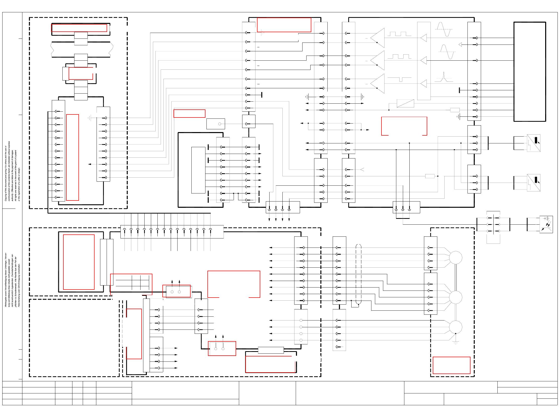
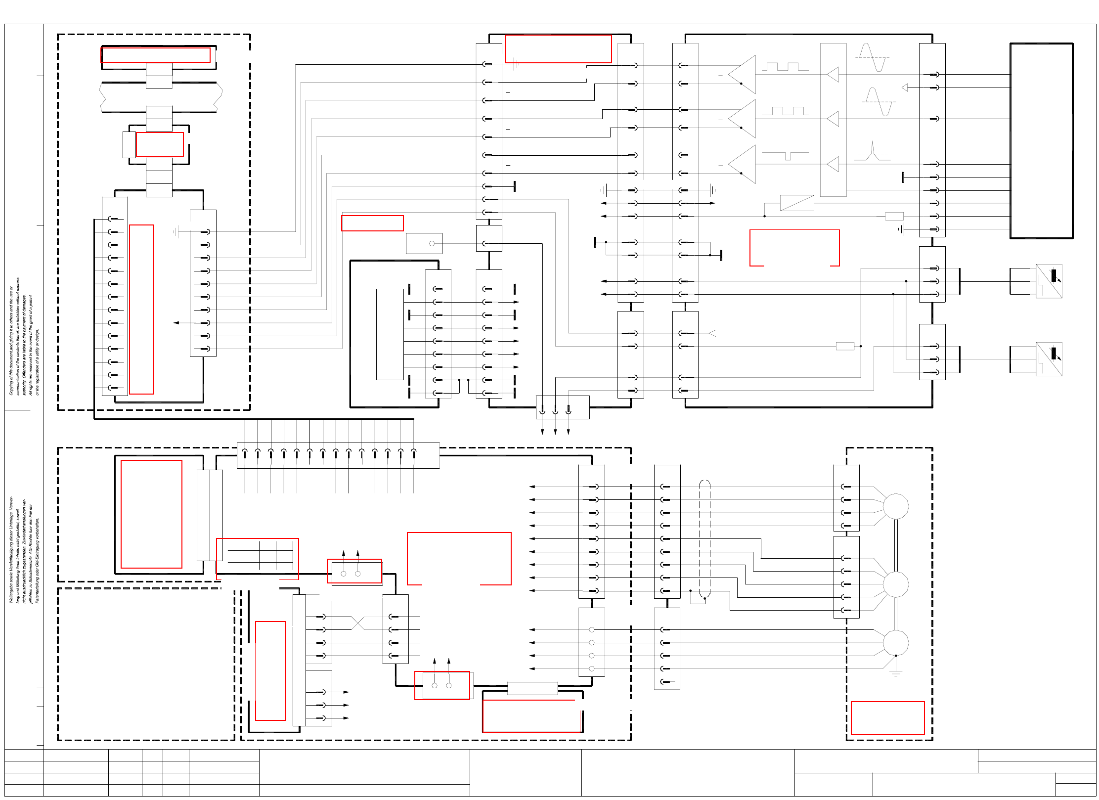
2 Detailed circuit diagrams 18
Y2-S25 Y-axis, gantry 2, SIPLACE S-25 HM
27
26 Track N
Track N27
26
X1bb
00321558-xx
6
5
2
3
29
30
33
32
X11ba
(Cable)
Track B
Track B29
30
Track A
Track A
33
32
X23ba
10
12
13
A
A
B
B
N
N
15V
5V
+15V
+5V
U/2
2525
2222
-15V
-15V
+15V
28
31
28
31
T
T
20
21
GND
+24V
20
21
GND
+24V
X5bb
5
3
1
to X34ba
0/155V
+15V4
1,2
X7vn
-
3
X5vn
Gantry 1
Gantry 2
Switch
21
S1
1
S2
2
2
1
X11b
2
1
X6vn
-15V
+15V
X4vn
GND
Ready out
Enable
Ready
1
3
2
4
GND
I²t
Axis GND
V nom
8
5
6
7
9
10
11
Tacho-std
00343908-xx
Y-axis (gantry 2)
A24 (vn)
Servo unit backplane
Tacho-std2
1GND
X3vn
Force
GND
13
12
14
X2vn
W3br3
4 ye/gn 4
5
(cable W2)
00337066-xx
00337538-xx
X8vn
2
1
(cable)
bl
bk
RSE W 7
8
10
RSE U
RSE V
6
5
2
X6bb
3
5
1
X2bb
27
26
24
23
X10ba
24
23
26
27
Limit switch
X-axis loop
Conversion board
00336689-xx (bb)
large axis
bl
br
bk
bl
br
bk
bk
br
bl -
+
A1
bl -
A1
br +
bk
00300601-xx
(Cable)
00300905-xx
(Cable)
End pos. prox. switch B1
Y-axis Y-axis
End pos. prox. switch B2
X34ba
7
5
Control unit
Power supply
00356211-xx
00334520-xx
+24V
00344218-xx
(cable)
+5V
+15V
-15V
9
8
7
6
5
+5V
-15V
+15V
+5V
+24V
X19
2
3
4
Machine controller M54 A1 (sa)
00356211-xx
Control unit
Cable 00344246-xx
rd
nom. values
Y-axis
109
Axis rear panel gantry 2 A29 (uc)
14
12
13
10
11
12
13
00344255-xx
(Cable)
X1su
X3uc
7
8
5
6
00345015-xx
3
4
1
2
8
9
5
6
2
3
X5su
X1tq
A6 (tq)
SMP bus A32 (su)
Axis board
X24
X7uc
X2tq
X3tq
Y-axis
axis tracks
X1sa
GND
GND
Track B
3
4
2
1
Track A
Y-axis incremental shaft encoder
X4bb
6
9
8
7
5
gnwh
bk
rd
bl
wh
br
ye
pk
gn
Zero pulse
Signal
(Track N)
Screen
LED
GND
+5V
LED
00300608-xx
(Cable)
8
9
AenderungZustand Datum
CAD-Datei : Y2-S25.DWG
Urspr./Ers.f./Ers.d.NormName
Gepr.
Stromlaufplan/Circuit diagram
PL EA
Mat.-Nr. :
Beab. Hi
Datum 29.01.01
SIEMENS
SMD Placement System SIPLACE S-25 HM
1
1
Y-axis, gantry 2
SIPLACE S-25 HM
X4uc
X12ba
1
+5V
00336690-xx (ba)
Gantry conversion board
Reference point
End position
prox. switch 1
X-axis enable for y
6
X35ba
2
00357878-xx
Terminal strip
X2kf
2
(cable)
00344225-xx
wh
(lefthand side)
gantry 2
Distance sensor
00321557-xx
(cable)
1,17,18,19,34
1,4,7,17,20
1,4,7,17,20
(Gantry 2)
service
Axis
8
9
7
6
5
4
1
3
2
bl
rd
pk
gr
ye
wh
gn
br
Power GND
Motor W
Motor V
Motor U
RSE GND
RSE +5V
Tacho Mp
Tacho W
Tacho V
Tacho U
00344206-xx A14 (vn)
DBM / 3P - 3
Dynamic brake
Precontrol-
Power GND
X1 plug assignment / servo amplifier
RLG U
Tacho W
Precontrol+
12z
12b
12d
RLG W
Tacho std
Enable input
Ready
Brake out
Tacho V
+15V8z
10d
10b
10z
8b
8d
6b
28d,z,b
32d,z,b
30d,z,b
Motor U
Motor V
18d
16z
20d,z,b
26d,z,b
18b
18z GND
+Ub
Motor W
-15V
+15V
GND
Y-axis servo amplifier
TBF 120 / 12 TS
00337626-xx
Nom+
Tacho Mp
Neg. stop
Pos. stop
Nom-
4b
4z
4d
2b
2d
14b
14d
16d
14z
16b
Force
I²t
RLG V
signal
Tacho U
00343723-xx
Servo unit
A7 (vn)
X1
00337333-xx A15
Anti-crash board
Ready33
Conversion board
X1
5
gantry
X11f
7
4
Y-axis
9
Encoder
RSE = Rotary Shaft
Y-axis
End position
prox. switch 3
End position
prox. switch 1
End position
prox. switch 2
Sheet
Sh.
1
X31b
V
U
4
12
11
3
00337539-xx
X1vn
4
3
1
2
(cable)
10
2
X32b
1
9
rdV
Y motor S-23
00337066-xx
M
W
ye/gn
ye
3~
U
RSE GND
RSE +5V
RSE W
RSE V
RSE U
RSE
bk
vi
rd
2
4
XR
wh/br
wh/bk
or
5
3
1
Tacho Mp
Tacho W
Tacho V
Tacho U
XT
gn
br
wh
ye
4
3
T
1
2
To plug 11f anti-crash board
6
13
00337066-xx
(cable W1)
(cable)
00321571-xx
9
25 25
5
X7bb
1
3
br
wh
gn
(Cable)
00321576-xx
gn
br
wh
bk
rd
wh
X40
(Cable)
00321471-xx
bk
rd
wh
-+A1
Distance light barrier B1
See page 65
See page 86
See page 132
See page 131
See page 28
See page 65
See page 93
See page 79
See page 27
See page 73
See page 81
See page 80
See page 141
See page 74