S25 circuit.pdf - 第32页
2 Detailed circuit diagrams 32 LP4- S25 PCB c onv eyor 1, wi dt h adj ust men t Moto r, wi dth ad justm ent narrow er, con vey or 1 Moto r, wi dth ad justm ent wid er, c onveyor 1 Position width adjustment 1 00326017-xx …
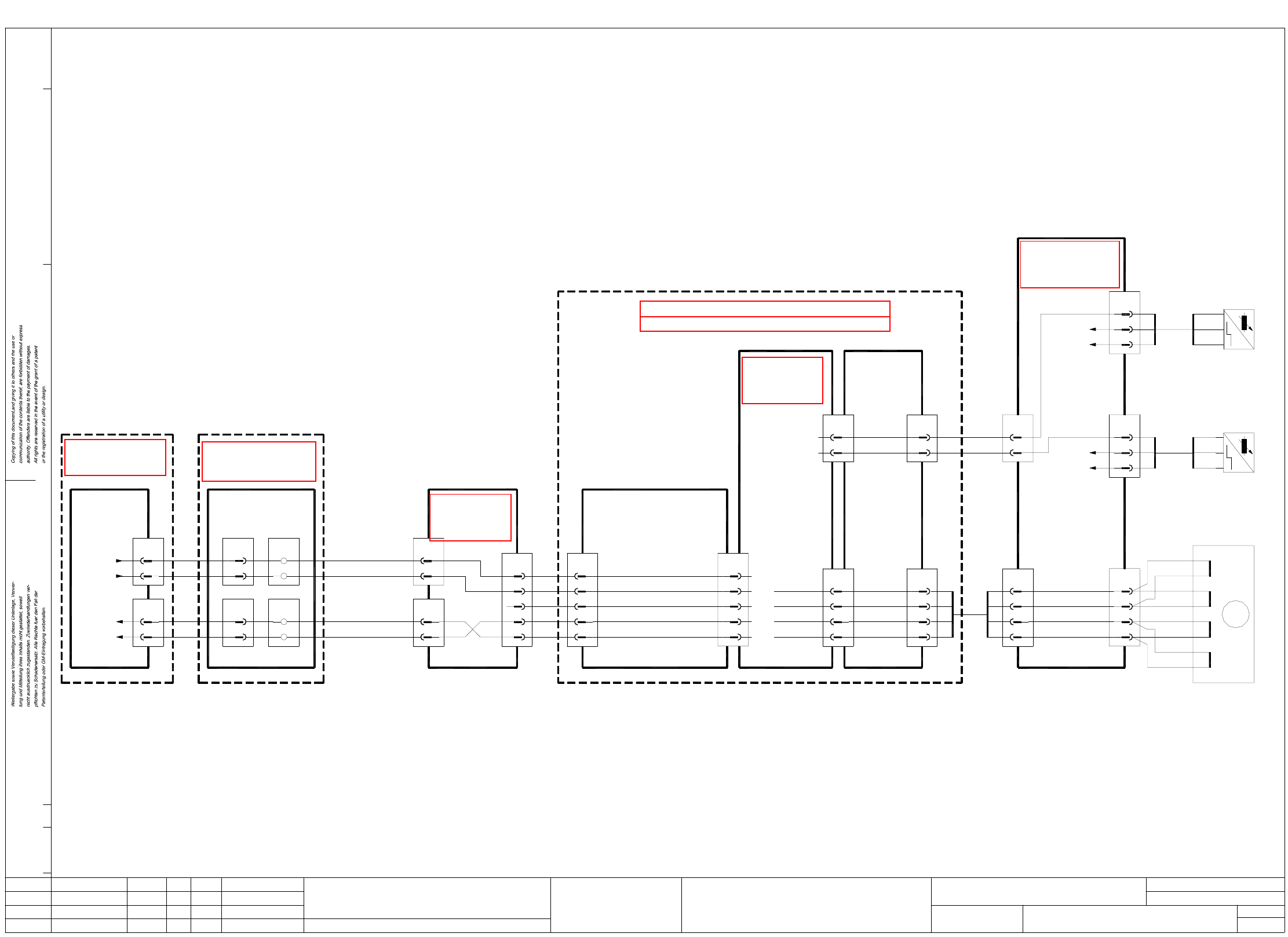
2 Detailed circuit diagrams 31
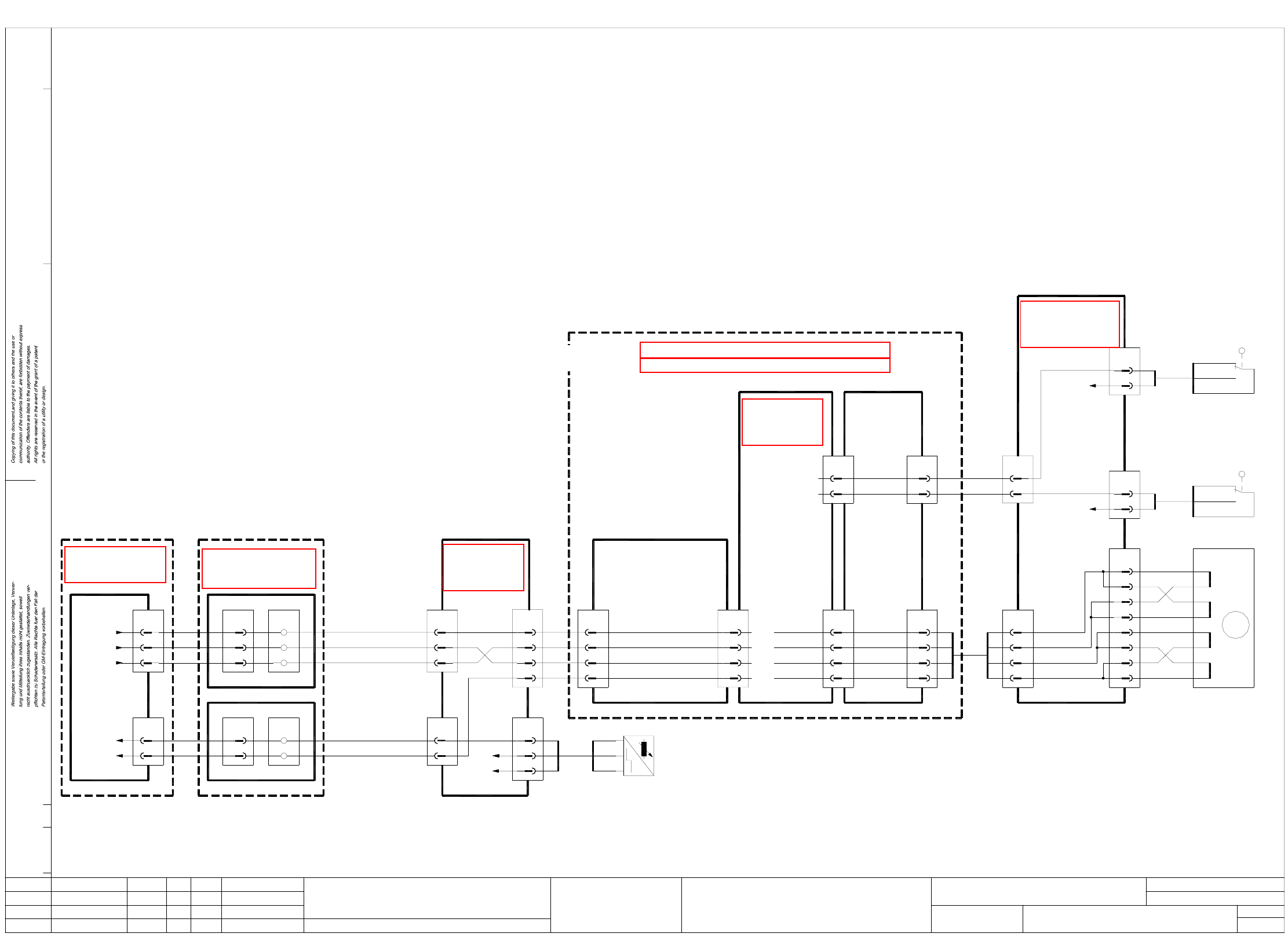
LP3-S25 PCB conveyor 1, lifting table control
10a,10c
8a,8c
6a,6c
4a,4c
X2a
X1a
18a
17a
4
3
2
1
X4a
12
X3a
10
00325580-xx
Dual stepping
Backplane
wh
br
gn
ye
motor board
Stroke 1 B+
Stroke 1 B-
Stroke 1 A+
Stroke 1 A-
Sensor switch
Lifting table bottom
Sensor switch
Lifting table top
14c
22a
X1a
13c
14a
Dual stepping
00325579-xx
motor board
22c
X3a
20
19
4
5
3
Dual stepping
00325580-xx
Backplane
motor board
Control unit - single conveyor 00331465-xx
Control unit - dual conveyor 00327615-xx
Lifting table 1 down
Lifting table 1 fast/slow
End signal, lifting table 1 bottom
End signal, lifting table 1 top
Lifting table 1 up
00326064-xx
(Cable)
X8
20
19
4
5
3
br
GND
10
X8
+24VDC
X28
2
3
6
bk
br
bl
lifting table 1 bottom
Sensor switch,
00326021-xx
bk
br
bl
A1
+
-
'dual conveyor'
Conversion board
00325581-xx
+24VDC
GND
6
3
bl
br
X26
2
bk
lifting table 1 top
Sensor switch,
bl
br
-
+
00326020-xx
bk A1
X14
2
3
1
orwh
rd
or
4
br
brwh
rdwh
yewh
ye
lifting table 1
00326034-01
Motor
+
-
-
+
+
-
-
+
A
A
B
B
M
12
X9
6
5
7
8
wh
ye
gn
Stroke 1 B+
Stroke 1 A-
Stroke 1 B-
Stroke 1 A+
Conversion board
00325581-xx
'Dual conveyor'
X12
1
2
X13
4
5
X1kb
X1ka
X2kb
X2ka
6
5
5
6
1
A1
2
2
1
wh
br
gr
ye
00357878-xx
left-hand side
Terminal panel
conveyor 1
Lifting table 1 down
Lifting table 1 up
conveyor 1
Lifting table 1 top
Lifting table 1 bottom
End signal
End signal
00326068-xx
(Cable)
(Cable)
00326069-xx
Port E1.1
Port E1.0
X4se
6
X2se
6
5
5
I/O cards
Port A1.1
Port A1.0
00344228-xx
(Cable)
00344230-xx
(Cable)
00326061-xx
(Cable) (Cable)
00326064-xx
Control unit
00356211-xx
Sheet
Sh.
AenderungZustand Datum
CAD-Datei : LP3-S25.DWG
Urspr./Ers.f./Ers.d.NormName
Gepr.
Stromlaufplan/Circuit diagram
PL EA
Mat.-Nr. :
Beab. Hi
Datum 29.01.01
SIEMENS
SMD Placement System SIPLACE S25 HM
1
1
PCB conveyor 1
Lifting table control
See page 115
See page 90
See page 94
See page 65 See page 86
See page 115
See page 114
2 Detailed circuit diagrams 32
LP4-S25 PCB conveyor 1, width adjustment
Motor, width adjustment
narrower, conveyor 1
Motor, width adjustment
wider, conveyor 1
Position width adjustment 1
00326017-xx
bk
br
bl
A1bk
bl -
br +
Sensor switch,
wider
End position:
+24VDC
gn
wh
3
4
2
1
adjustment 1
width adjustment 1
Limit switch
width adjustment 1
Limit switch
2
1
4
4
2
1
Sheet
Sh
.
X13
2
3
X1kb
X1kg
X2kb
X5kg
9
8
10
11
6
A1
7
5
4
ye
gr
gn
br
00357878-xx
left-hand side
Terminal panel
width adjstm., conveyor 1
conveyor 1
Sensor switch: position
End signal: width adjstm.
00326068-xx
(Cable)
(Cable)
00326069-xx
Port E1.4
Port E1.3
X4se
9
X3sf
11
10
8
I/O cards
Port A4.6
Port A4.5
00344233-xx
(Cable)
00344230-xx
(Cable)
00326061-xx
(Cable) (Cable)
00326064-xx
Control unit
00356211-xx
A4
5
wh9
9
Port A4.4
1
6
9
8
X8
6
17
+24VDC
GND
fast, conveyor 1
Motor, width adjustment
AenderungZustand Datum
CAD-Datei : LP4-S25.DWG
Urspr./Ers.f./Ers.d.NormName
Gepr.
Stromlaufplan/Circuit diagram
PL EA
Mat.-Nr. :
Beab. Hi
Datum 29.01.01
SIEMENS
SMD Placement System SIPLACE S25 HM
1
1
PCB conveyor 1
Width adjustment
rd
11
X8
+24VDC
X32
2
3
narrower
00326019-xx
br
gn
wh
'dual conveyor'
Conversion board
00325581-xx
3
2
wh
gn
X30
wider
wh
gn
00326018-xx
br
X16
6
7
5
orwh
rd
or
8
br
brwh
rdwh
yewh
ye
width
00326033-xx
Motor
+
-
-
+
+
-
-
+
A
A
B
B
M
13
X9
2
1
3
4
bl
pk
gr
Width 1 B+
Width 1 A-
Width 1 B-
Width 1 A+
20a/c
18a/c
15a/c
14a/c
X2a
X1a
18c
17c
8
7
6
5
X4a
13
X3a
11
00325580-xx
Dual stepping
Backplane
gr
pk
bl
rd
motor board
Width 1 B-
Width 1 B+
Width 1 A-
Width 1 A+
width adjustment 1
narrower
End position:
width adjustment 1
16a
16c
X1a
15a
Dual stepping
00325579-xx
motor board
21a
X3a
17
9
6
8
Dual stepping
00325580-xx
Backplane
motor board
Control unit - single conveyor 00331465-xx
Control unit - dual conveyor 00327615-xx
Width adjstm. 1 fast
Width adjstm. 1 wider
Width adjstm. 1 narrower
End pos., width adjstm. 1
00326064-xx
(Cable)
X24
3
2
Conversion board
00325581-xx
'Dual conveyor'
X12
4
5
See page 115
See page 90
See page 94
See page 65 See page 86 See page 115
See page 114
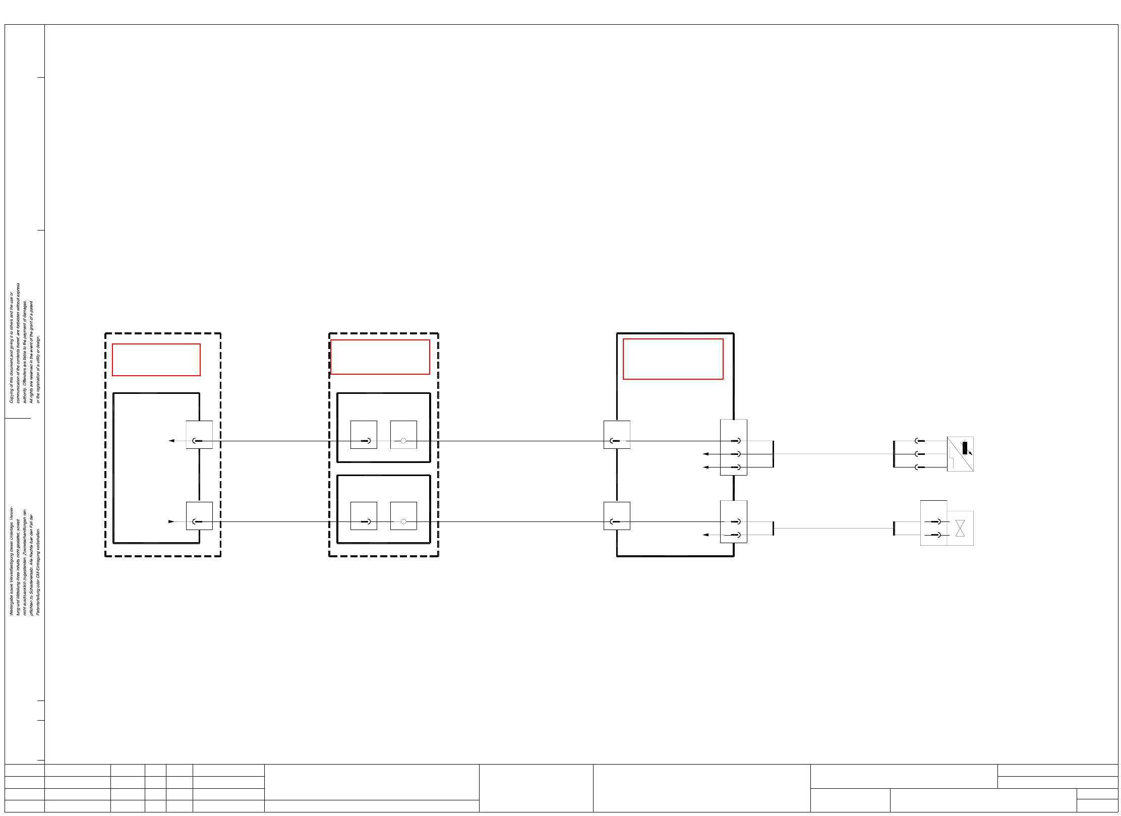
2 Detailed circuit diagrams 33
LP5-S25 Ceramic substrate centering
(Cable)
00344230-xx
Conversion board
00325581-xx
'dual conveyor'
6
2
br
X48
GND
+24VDC
6
3
bl
br
2
X46
bk
12
Terminal panel
left-hand side
00357878-xx
X1kb
X1ka
12
12
8
A1
X2ka
8
A1
X2kb
X2se
12
X4se
00344228-xx
(Cable)
Port A1.7
Port E1.7
00356211-xx
Control unit
AenderungZustand Datum
CAD-Datei : LP5-S25.DWG
Urspr./Ers.f./Ers.d.NormName
Gepr.
Stromlaufplan/Circuit diagram
PL EA
Mat.-Nr. :
Beab. Hi
Datum 29.01.01
SIEMENS
SMD Placement System SIPLACE S25 HM
1
1
PCB conveyor 1
Ceramic substrate centering
X13
7
X12
7
00326069-xx
(Cable)
00326068-xx
(Cable)
bl
bl
Sensor switch
Valve, ceramic substrate centering 1
Ceramic substrate centering 1
Ceramic substrate
Sensor switch
bk
GND
br
bl -
+
bk A1
(Cable)
00326029-xx
B1
2
1
X40
br
wh
00326028-xx
Valve
centering 1
centering 1
Ceramic substrate
Sheet
Sh.
See page 115
See page 86See page 65