S25 circuit.pdf - 第51页
3 Circ uit d iagrams 51 001 18250-0 10101LD 2 Z-diagram, PCB conveyor 2 (Sh. 7 of 7) Proximity swit ch Limit switch C 12 (Conveyor 2) 9 B B X41 X33 X29 46 H A Sonar proximity switch B C 11 5 X27 X27 X29 00326035-xx (Conv…
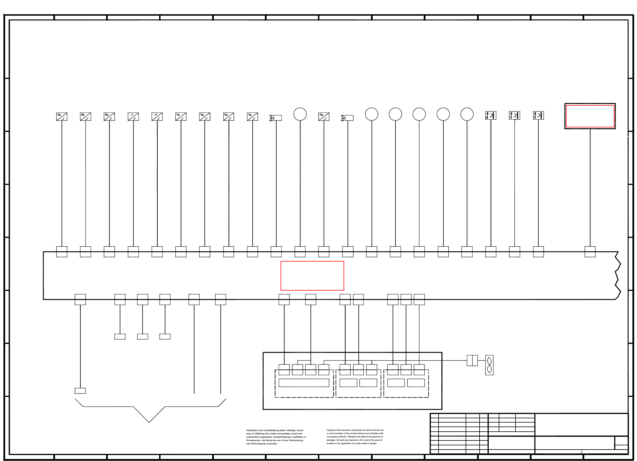
3 Circuit diagrams 50
00118250-010101LD2 Z-diagram, PCB conveyor 1 (Sh. 6 of 7)
X3X2
00331297-xx
X3X2
Motor
X6
M
00326070-xx
X3
Fan
X4
00327615-xx
3
X22
8
X14
X2
Stroke/width 1
X5
(conveyor 1)
Light barrier, input conveyor
X52
X4
00330945-xx
X1
Light barrier, center conveyor
X32
Limit switch
H
9
X5d
X44 X48
C
00326021-xx
00326028-xx
ceramic substrate centering
Proximity switch
00326026-xx
Valve
X40
X40
4
F
(conveyor 1)
D
lifting table, top
M
output conveyor
(conveyor 1)
Proximity switch
lifting table width
X36
(conveyor 1)
center conveyor
(conveyor 1)
center conveyor
00329284-xx
X34
Motor
M
X4
X7
MM
Step motor control
A
11
B
X1
(conveyor 1)
(conveyor 1)
ceramic substrate centering
X18 X20
X44
X16
X42
X50 X56
X30
1
00326064-xx
X52
2
(conveyor 1)
79
C
step motor 'width narrower'
00326030-xx
X11
5
D
00326020-xx
11 12
A
H
Proximity switch
1
X30 X32
(conveyor 1)
lifting table, bottom
X4'
Proximity switch
6
X24
X24
00326017-xx
00326033-xx
00326034-xx
00330944-xx
5
(conveyor 1)
stopper
00329285-xx
X1
X5
00329283-xx
X4
X3'
X56
X5d
00326063-xx
(conveyor 1)
Proximity switch
Limit switch
X2
X2
F
H
X13
7
X9
X13
X48 X54X46X26 X28
X38
00326024-xx
00326061-xx
7
3
G
H
G
X10
X10
00326065-xx
width adjustment
X11
00326062-xx
10
X14
X3
X16
1212
G
X18 X20
X5
X5'
4
00326029-xx
X9
X8
00326031-xx
G
X38
68
2
X14
(conveyor 1)
X12
See
X34
00326022-xx
00326027-xx
sheet 5
D
C
adhesive wiper facility
X12
00326069-xx
00326068-xx
00325581-xx
X8
00326067-xx
X5
X5
Valve
M
Motor
(conveyor 1)
X46
00326019-xx
00326018-xx
PCB conveyor control 1
10
11
X22
E
F
7
input conveyor
output conveyor
Bosch specialdesign
X50
PL EA1 E
SIEMENS AG
Zust. Aenderung Datum Name (Urspr.)
Tu.18.09.00Product status01
01 Document status 18.09.00 Tu.
01 Function status Tu.18.09.00
(Ers. f.:) (Ers. d.:)
00118250-010101LD2
7
Sh.
6
Sheet
18.09.00
Norm
Gepr.
Datum
Bearb.
SIPLACE 80S25HM1Tuth
Z-diagram, PCB conveyor 1
Name
input conveyor
Sonar proximity switch
(conveyor 1)
step motor 'width wider'
12
X6 X7
10
A
12
E
F
E
(conveyor 1)
stopper
8
X3
X4X3
Half bridge
X4
X28X26
X4
Motor
Motor
98
3
E
3
6
4
X1
10
lifting table
Stroke/width 2
(conveyor 1)
(conveyor 1)
(conveyor 1)
X5
X4X3
X54
X3
00330946-xx
X2
(conveyor 1)
00326032-xx
(conveyor 1)
Light barrier, output conveyor
Ceramic substrate
X42
centering
00330950-xx
92 6
D
5
B
C
1151
00326025-xx
Motor
A
4
BB
X5
Sonar proximity switch
(conveyor 1)
X36
X1
00326023-xx
X5
Sonar proximity switch
(conveyor 1)
S
ee page 29
S
ee page 33
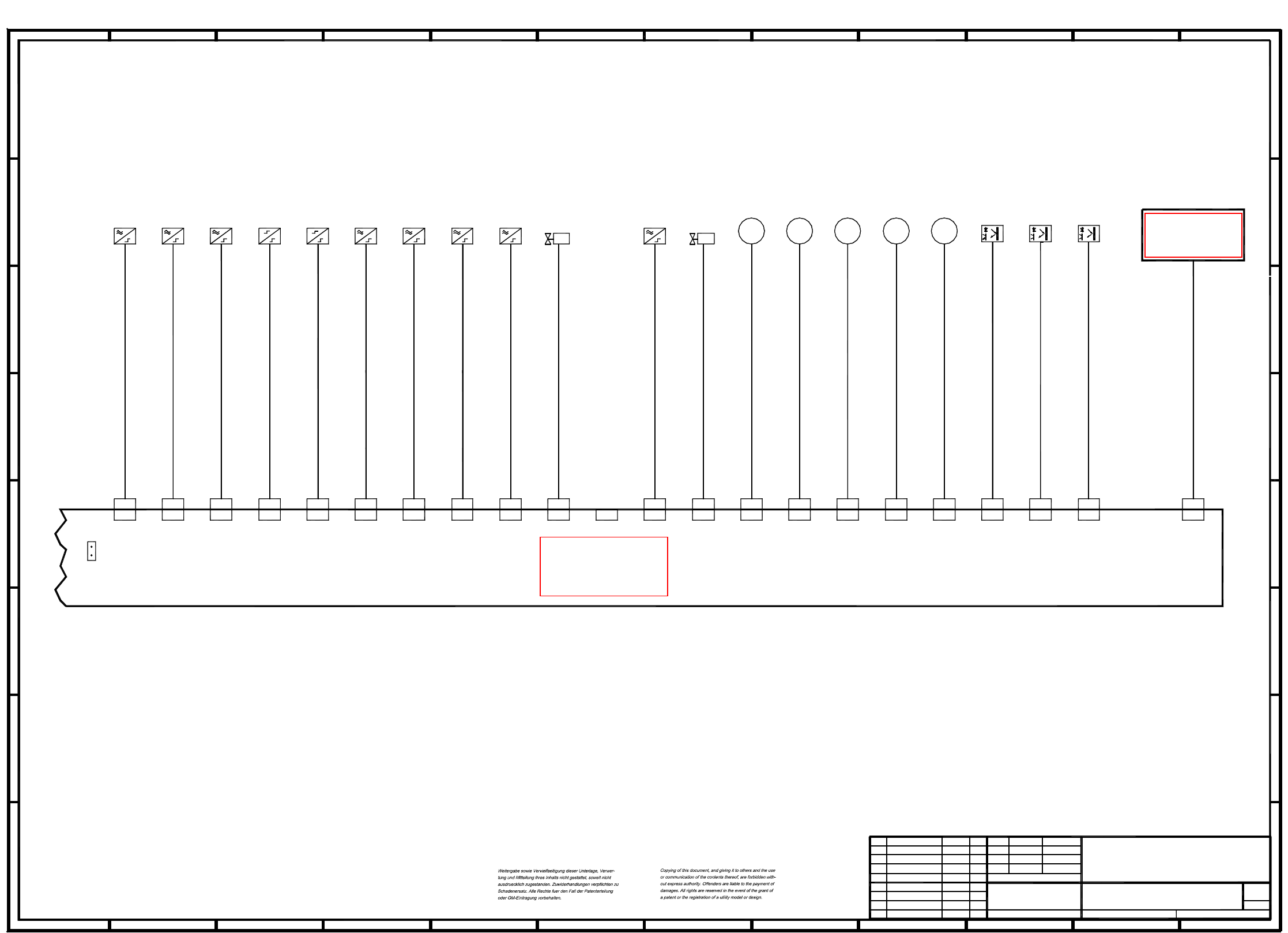
3 Circuit diagrams 51
00118250-010101LD2 Z-diagram, PCB conveyor 2 (Sh. 7 of 7)
Proximity switch
Limit switch
C
12
(Conveyor 2)
9
BB
X41X33X29
46
H
A
Sonar proximity switch
B
C
115
X27
X27 X29
00326035-xx
(Conveyor 2)
Proximity switch
PCB conveyor control 2
X55
G
H
G
CC
00326044-xx
X19 X21
X33
(Conveyor 2)
Motor
Stopper
Proximity switch
5
X49
X49X43
Output conveyor
Sonar proximity switch
9
X53
Input conveyor
Width adjustment
Output conveyor
Bosch special design
(Conveyor 2)
X31
1
X39
X39
00326043-xx
M
9
3
6
M
(Conveyor 2)
H
A
8
00330948-01
8
*X
43
X47
Ceramic substrate
centering
00330951-01
9
8
* Insert jumper X
for dual conveyors
00326036-xx
X23 X17 X15 X51 X57
X15 X51 X57
MM
lifting table width
5
X47
(Conveyor 2)
X53X19
1010
Motor
Motor
00325581-xx
D
(Conveyor 2)
X35
Motor
(Conveyor 2)
H
G
Ceramic substrate centering
3
EE
7
F
Proximity switch
Lifting table, top
X25
X25
X37
X37
00326042-xx
4
3 10
Light barrier Center conveyor
(Conveyor 2)
12
Input conveyor
Sonar proximity switch
(Conveyor 2)
(Conveyor 2)
Light barrier Output conveyor
00326045-xx
00326037-xx
G
00326051-xx
12
n. c.
2
X43
(Conveyor 2)
21 12
F
B
4
Ceramic substrate centering
Proximity switch
11
Lifting table
(Conveyor 2)
00326058-xx
D
11
11
X21
00326041-xx
Light barrier Input conveyor
(Conveyor 2)
7
X45
5
D
00326038-xx
00330947-xx
2
Valve
(Conveyor 2)
(Conveyor 2)
00326039-xx
00326049-xx
X31
M
00326056-xx
X55
00330949-01
(Conveyor 2)
F
X17X23
7
Step motor 'Width wider'
(Conveyor 2)
Lifting table, bottom
(Conveyor 2)
6
D
00326052-xx
Limit switch
00326053-xx
X35
Valve
X41
E
F
E
(Conveyor 2)
1
Motor
1 6
2
Stopper
10
A
Center conveyor
Center conveyor
8
Step motor 'Width narrower'
00326054-xx
A
(Conveyor 2)
7
PL EA1 E
SIEMENS AG
Zust. Aenderung Datum Name (Urspr.)
Tu.18.09.00Product status01
01 Document status 18.09.00 Tu.
01 Function status Tu.18.09.00
(Ers. f.:) (Ers. d.:)
00118250-010101LD2
7
Sh.
7
Sheet
18.09.00
Norm
Gepr.
Datum
Bearb.
SIPLACE 80S25HM1Tuth
Z-diagram, PCB conveyor 2
Name
S
ee page 34
S
ee page 33
3 Circuit diagrams 52
00116900-020101FD3 Input/output assignment, Siplace S-25 HM (Sh. 1 of 2)
Zustand
1.
1.
2.
CAD-Datei :
Datum
13.01.97
Aenderung
Gepr.
NormName
Wer
Urspr./Ers.f./Ers.d.
116900F1
Pins marked with an '*' are not hard-wired.
14.08.1995
13.01.97
13.01.97
1
Datum
Beab.
Wer
Wer
Haas
2
X5se:13-14
X5se:12
A2/X2kd:M
A2/X2kd:8
Mat.-Nr. :
34
00116900
56
Control on, 1 -> K1/K2 on
GND
A2/X2kd:3
X5se: 9
X5se:10
X5se:11
X5se: 8
X5se: 7
A2/X2kd:5
A2/X2kd:6
A2/X2kd:7
A2/X2kd:4
X5se: 6
X5se: 5
X5se: 1-4(*)
A2/X2kd:1
A2/X2kd:2
A2/X2kd:P
Protective cover, 1 -> opened
'On' button, 1 -> actuated
'Off' button, 0 -> actuated
Key-operated switch, 0 -> actuated
Compressed air sensor, 1 -> compressed air available
Control on, 1 -> K3/K4 on
EMERG-.STOP button, 1 -> actuated
+24VDC
X4se: 9 A1/X2kb:5
X4se:11
X4se:13-14
X4se:12
X4se:10
A1/X2kb:7
A1/X2kb:M
A1/X2kb:8
A1/X2kb:6
X4se: 8
X4se: 7
X4se: 6
X4se: 5
A1/X2kb:4
A1/X2kb:3
A1/X2kb:2
A1/X2kb:1
Limit switch, width adjustment, conveyor 1
Contactor monitoring (software release)
Bero, ceramic substrate centering, conveyor 1
Bero, stopper 1 retraced, conveyor 1
GND
Bero, stopper 2 retracted, conveyor 2
Bero, position width adjustment, conveyor 1
Bero, lifting table bottom pos. conveyor 1
Bero, lifting table top pos., conveyor 1
Ultrasonic sensor, output conveyor, conveyor 2
Pins marked with an '*' are not hard-wired !
G
N
D
SIPLACE 80S20
AUT 5
Stromlaufplan/Circuit diagram
7
SIEMENS
89
Port E2.7
Input/output assignment
10 11 12
X5sf:12
X5sf:13-14 A4/X5kg:M
A4/X6kg:8
00116900-020101FD3
Sh.
Sh.
13 14 15 16 17 18
Port E4.7
Ultrasonic sensor, input conveyor, conveyor 2
Ultrasonic sensor, center conveyor, conveyor 2
Ultrasonic sensor, center conveyor, conveyor 1
Bero, nozzle changer SP portal 2 opened
Bero, nozzle changer SP portal 1 opened
Bero, nozzle changer SP portal 1 closed
Bero, nozzle changer SP portal 2 closed
Distance sensor
Crash, portal I
GND
+24VDC
'Request' to conveyor 1 from previous station
'Transferred' to conveyor 1 from previous station
'Permission' to conveyor 1 from following station
'Received' to conveyor 1 from following station
Ultrasonic sensor, input conveyor, conveyor 1
Ultrasonic sensor, output conveyor, conveyor 1
Port E2.4
Port E2.5
Port E2.6
Port E2.3
Port E2.2
Input
Port E2.1
Port E2.0
A4/X4kg:15
X5sf: 9
X5sf:10
X5sf:11
X5sf: 7
X5sf: 8
A4/X6kg:5
A4/X6kg:7
A4/X6kg:6
A4/X4kg:14
X5sf: 5
X5sf: 6
X5sf: 1-4(*)
A4/X3kg:18
A4/X3kg:19
A4/X5kg:P
Input
Port E1.4
Port E1.6
Port E1.7
Port E1.5
Port E1.3
Port E1.2
Port E1.1
Port E1.0
X4sf: 9 A3/X2kf:5
X4sf:11
X4sf:12
X4sf:13-14
X4sf:10
A3/X2kf:7
A3/X2kf:M
A3/X2kf:8
A3/X2kf:6
X4sf: 7
X4sf: 8
X4sf: 5
X4sf: 6
A3/X2kf:4
A3/X2kf:3
A3/X2kf:2
A3/X2kf:1
Port E4.4
Port E4.5
Port E4.6
Port E4.3
Port E4.2
Input
Port E4.1
Port E4.0
Input
Port E3.4
Port E3.6
Port E3.7
Port E3.5
Port E3.3
Port E3.2
Port E3.1
Port E3.0
X3se: 7 Lamp, main fault indicator lefthand side (white)A2/X2kc:3
X4se: 1-4(*)
X3se:13-14
X3se:12
A1/X2kb:P
A2/X2kc:M
A2/X2kc:8
X3se:11
X3se:10
X3se: 8
X3se: 9 A2/X2kc:5
A2/X2kc:6
A2/X2kc:7
A2/X2kc:4
Software release, control on
+24VDC
GND
Command 'read PCB barcode' 2 (contactor relay)
Command 'read PCB barcode' 1 (contactor relay)
MC1 (M44)
Icos MC1
X3se: 6
X3se: 5
X3se: 1-4
A2/X2kc:1
A2/X2kc:2
A2/X2kc:P
Lamp, main fault indicator ready (green)
Lamp, main fault indicator righthand side (white)
+24VDC
Plug desig. I/O terminal Signal designation
Motor, output conveyor on slow 1, conveyor 1X2sf: 9
Output
Output
Port A3.4Port A1.4
Motor, PCB input conveyor on fast, conveyor 1
Component counter
GND
GND
+24VDC
+30VDC switched
Motor, output conveyor on fast, conveyor 1
Motor, output conveyor on slow 2, conveyor 1
X3sf: 7Port A2.2
Port A2.7
Port A2.6
Port A2.5
Port A2.3
Port A2.4
Output
X4sf: 1-4(*)
X3sf:13-14
X3sf:12
A3/X2kf:P
X3sf:11
X3sf:10
X3sf: 9
X3sf: 8
Port A2.1
Port A2.0
Port A1.7
Port A1.6
Port A1.5
X3sf: 6
X3sf: 5
X3sf: 1-4
X2sf:12
X2sf:13-14
X2sf:10
X2sf:11
Port A4.2
Port A4.7
Port A4.6
Port A4.5
Port A4.3
Port A4.4
Output
Port A4.1
Port A4.0
Port A3.7
Port A3.6
Port A3.5
Signal designation
+30VDC switched
Motor, spare, on slow
Motor, spare, on fast
Motor, center conveyor on slow, conveyor 1
Motor, center conveyor on fast, conveyor 1
Port A1.2
Port A1.3
Port A1.1
Port A1.0
Address
X2sf: 7
X2sf: 8
X2sf: 5
X2sf: 6
X2sf: 1-4
Plug desig. I/O terminal
Port A3.2
Port A3.3
Port A3.1
Port A3.0
Address
A4/X3kg:15
A4/X3kg:14
A4/X4kg:19
A4/X4kg:18
A4/X5kg:5
A4/X5kg:6
A4/X5kg:7
A4/X5kg:8
A4/X5kg:G
A4/X5kg:M
Motor, width adjustment wider, conveyor 1
Motor, width adjustment narrower, conveyor 1
Motor, width adjustment fast, conveyor 1
'Transferred' to following station from conveyor 1
'Request' to following station from conveyor 1
'Received' to previous station from conveyor 1
'Permission' to previous station from conveyor 1
Conversion
board,
PCB handling
A1/X2ka:1
A1/X2ka:2
A1/X2ka:3
A1/X2ka:4
A1/X2ka:5
A1/X2ka:6
A1/X2ka:7
A1/X2ka:8 Valve, ceramic substrate centering, conveyor 1
Valve, extend stopper 1, conveyor 1
Compressed air on/off
Valve, nozzle changer 1 opened
Valve, nozzle changer 2 opened
Retract lifting table, PCB release, conveyor 1
A1/X2ka:P
A1/X2ka:M
+24VDC
GND
Valve, extend stopper 2, conveyor 2
X2se:13-14
X2se:12
X2se:11
X2se:10
X2se: 9
X2se: 8
X2se: 7
X2se: 6
X2se: 5
X2se: 1-4
Extend lifting table, PCB clamping, conveyor 1
Function status
Product status
Documentation status
SMD Placement System Siplace 80S20
1
2