S25 circuit.pdf - 第54页
3 Circ uit d iagrams 54 0033681 2-020 101FD3 Circuit di agram overview, safety conce pt (powe r unit) (Sh. 1 o f 3) Doc. sta tus Funct ion status Safety concept (power unit) = Datum Gepr. Norm Bearb. Sheet Urspr. Ers. f.…
3 Circuit diagrams 53
00116900-020101FD3 Input/output assignment, Siplace S-25 HM (Sh. 2 of 2)
SIEMENS
91011
'Request' to conveyor 2 from previous station
'Transferred' to conveyor 2 from previous station
'Received' to conveyor 2 from following station
'Permission' to conveyor 2 from following station
Bero, ceramic substrate centering, conveyor 2
Bero, lifting table top position, conveyor 2
Bero, lifting table bottom position, conveyor 2
Limit switch, width adjustment, conveyor 2
Bero, position width adjustment, conveyor 2
X5sg: 9
X5sg:11
X5sg:10
X5sg: 8
X5sg: 7
X5sg: 6
X5sg: 5
X5sg: 1-4(*)
A6/X5ki:15
A6/X6ki:5
A6/X6ki:7
A6/X6ki:6
A6/X5ki:14
+24VDC
A6/X5ki:18
A6/X5ki:19
A6/X5ki:P
X4sg: 9
X4sg:11
X4sg:13-14
X4sg:12
X4sg:10
X4sg: 8
X4sg: 7
X4sg: 6
X4sg: 5
GND
Port E6.4
Port E6.6
Port E6.5
Port E6.3
Port E6.2
Port E6.1
Port E6.0
Input
Port E5.4
Port E5.6
Port E5.7
Port E5.5
Port E5.2
Port E5.3
Port E5.1
Port E5.0
Input
18
00116900-020101FD3
12 13 14 15 16 17
Sh.
Sh.
Motor, output conveyor on slow 1, conveyor 2 Port A5.4X2sg: 9
Output
Valve, ceramic substrate centering, conveyor 2
Motor, width adjustment wider, conveyor 2
Motor, width adjustment narrower, conveyor 2
Motor, width adjustment fast, conveyor 2
'Permission' to previous station from conveyor 2
'Transferred' to following station from conveyor 2
'Request' to following station from conveyor 2
'Received' to previous station from conveyor 2
Motor, output conveyor on fast, conveyor 2
Motor, output conveyor on slow 2, conveyor 2
Motor, input conveyor on fast, conveyor 2
A6/X5ki:19X3sg: 7
X4sg: 1-4(*)
X3sg:12
X3sg:13-14
X3sg: 9
X3sg:10
X3sg:11
X3sg: 8
GND
+24VDC
A6/X5ki:M
A6/X5ki:8
A6/X5ki:5
A6/X5ki:7
A6/X5ki:6
A6/X5ki:18
X3sg: 5
X3sg: 6
X3sg: 1-4
X2sg:13-14
X2sg:12
X2sg:11
X2sg:10
+30VDC switched
A6/X5ki:15
A6/X5ki:14
A6/X5ki:G
GND
PCB handling
Port A6.2
Port A6.7
Port A6.6
Port A6.5
Port A6.4
Port A6.3
Output
Port A6.1
Port A6.0
Port A5.7
Port A5.6
Port A5.5
Extend lifting table, PCB clamping, conveyor 2
Retract lifting table, PCB release, conveyor 2
Motor, center conveyor on slow, conveyor 2
Motor, center conveyor on fast, conveyor 2
X2sg: 7
X2sg: 8
X2sg: 6
X2sg: 5
X2sg: 1-4
Plug desig.
board,
Conversion
+24VDC
Signal designationI/O terminal
Port A5.2
Port A5.3
Port A5.1
Port A5.0
Address
Conversion
board,
PCB handling
Function status
Product status
Doc. status
SMD Placement System Siplace 80S20
2
2
Stromlaufplan/Circuit diagram
SIPLACE 80S20
Input/output assignment
Mat.-Nr. :
CAD-Datei :
Urspr./Ers.f./Ers.d.AenderungZustand
1.
Datum
13.01.97
Name Norm
Wer
Gepr.
Pins marked with an '*' are not hard-wired !
1.
2.
13.01.97
13.01.97
1
X5sg:13-14
X5sg:12
14.08.1995
Datum
Wer
Beab.
Wer
Haas
234
GND
A6/X5ki:M
A6/X6ki:8
116900F2
AUT 5
00116900
5678
Port E6.7
3 Circuit diagrams 54
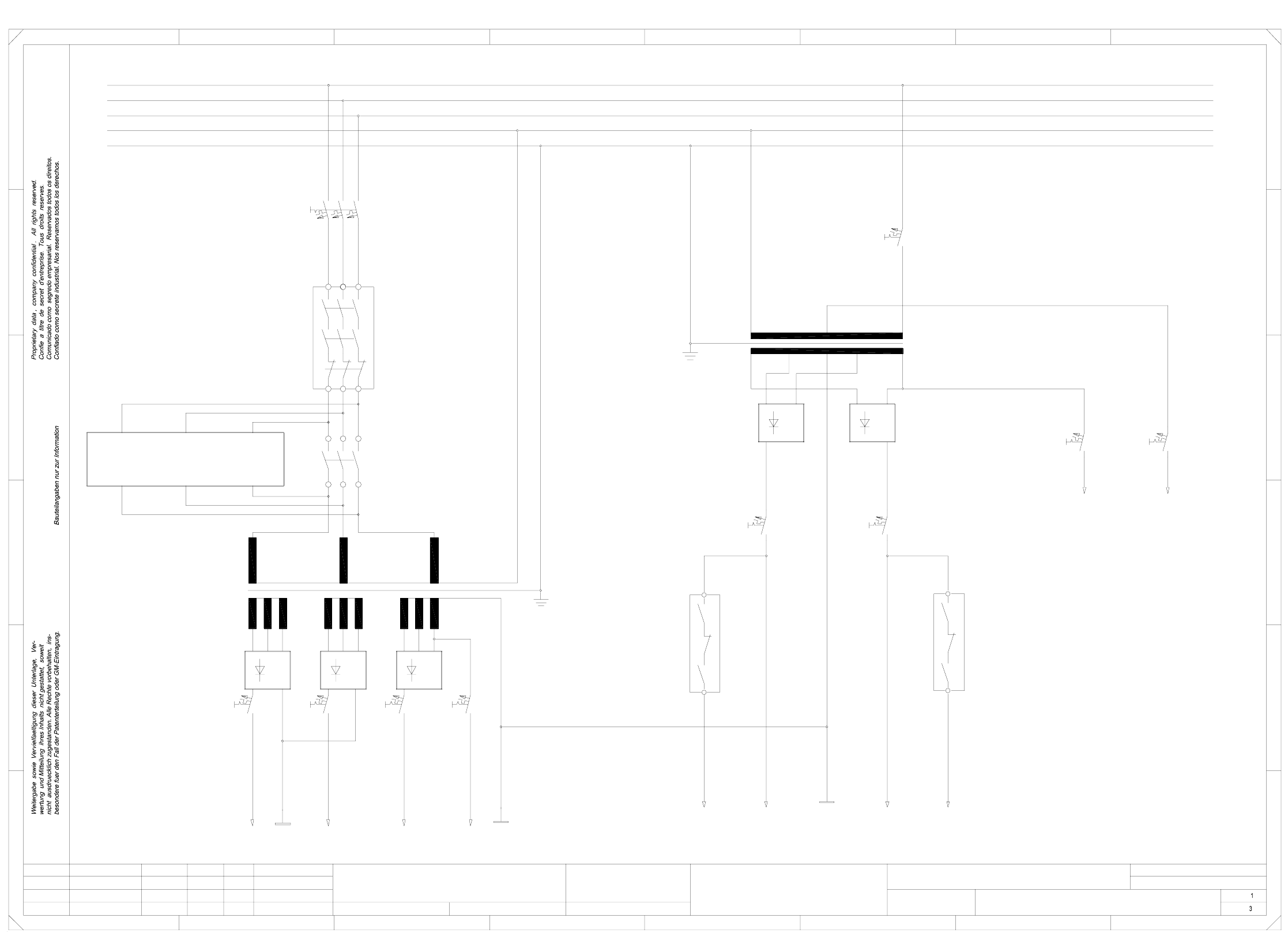
00336812-020101FD3 Circuit diagram overview, safety concept (power unit) (Sh. 1 of 3)
Doc. status
Function status
Safety concept (power unit)
=
Datum
Gepr.
Norm
Bearb.
Sheet
Urspr. Ers. f. Ers. d.NameDatumAenderungZustand
SIEMENS AG
Sh.
+
PL EA1 E
To
Inrush
current limiter
(ext. WPC)
K4
F4 F5
6L+
2L-
F10 F11
F3
23
24
L1
1L+
1L-
3L+2L+
4L+
V2
F7
T2
7L+
K1
L1
L2
L3
PE
N
5L+
K2
C
B
A
V4
13
K2
PE
L3
N
L2
2L-
V3
F6
V1
F9F8
F2
A1
T1
V5
14
23
FF
E
D
67
Switched
(Lifting table)
(dp1/Z axes)
(Star, slow)
(X,Y slow)
To
150VAC
safety circuit
24VAC
24VAC
(Tape cutter)
(Star/lifting table)
(X,Y axes)
451 67
B
C
D
E
8
12345
Leh
Leh
Leh
02
01
01
03.09.98
23.01.98
23.01.98
03.09.98
Werner
#
Circuit diagram overview
00336812-020101FD3
8
A
Switched
control unit
SMD-Placement System Siplace S23
Product status
3 Circuit diagrams 55
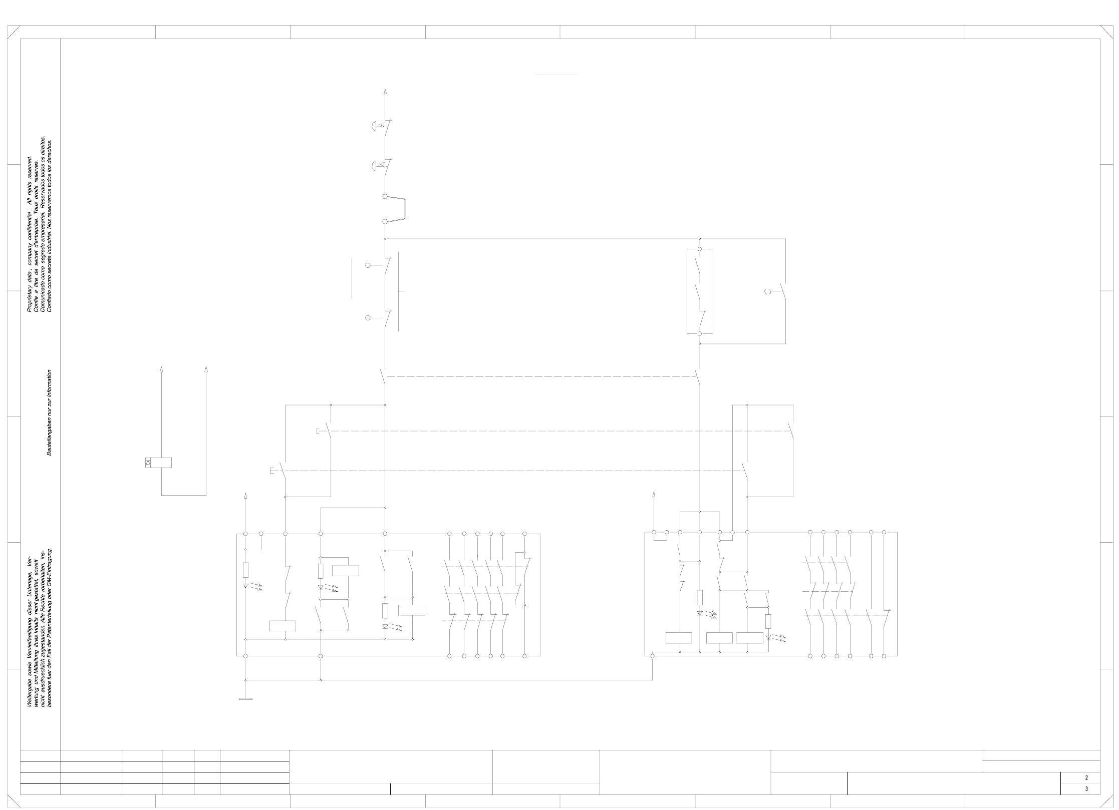
00336812-020101FD3 Safety concept overview (safety circuit) (Sh. 2 of 3)
=
Datum
Gepr.
Norm
Bearb.
Sheet
Urspr. Ers. f. Ers. d.NameDatumAenderungZustand
SIEMENS AG
Sh.
+
H2+H3 = Release signal
H3: LED, channel 1H1: POWER LED H2: LED, channel 2
(Output)
Software
3456
H2': LED Ready H1': LED Release signal
machine ON
release signal for
(Input)
(ON button)
Key-operated switch
Safety circuit
Emergency stop mushroom-head push-button
(output)
Emergency stop mushroom-head push-button
5678
12
FF
E
D
C
B
A
(input)
safety loops
Connection for external
Cover switch
1234
13
X6
24V AC
24
14 34 44 58 66
L1
K2 3TK2804-0AC2
K3'
K2'
H2'
K3'
K1' K3'
K1'
K2'
3323
K1 3TK2805-0AC2
K1'
K2'
H1
K3'
K2'K2'
K1' K3'
L2
K1' K2'
X1
(1-n)
Y0413-S1
X211
X211
Y0906-S1
Y0907-S1
~24VAC
H1'
3414 24
K1'
L1 X1
K1'
5743
44
E
78
A
B
C
D
K3'
K1' K2'
H2
H3
K1'
K2'
13
X5
X3
24V AC
X6
L2
C0952-K3
Y0438-S1
K3'
65
Y0906-S2
Y0907-S2
C0952-K3
44
54
66
X4
K1'
K2'
K3'
X5
K3'
X3
43
54
53
Y0907-S4
K1
65
X2 X4
01
01
02
Leh
Leh
Leh
53433323
K1
PL EA1 E
00336812-020101FD3
Safety concept overview
#
Werner
03.09.98
23.01.98
23.01.98
03.09.98
SMD-Placement System Siplace S23
Product status
Doc. status
Function status
(Safety circuit)