S25 circuit.pdf - 第80页
3 Circ uit d iagrams 80 0034390 7-010 102TD3 Servo u nit S25 , basic m odule (vi ewed f rom the fr ont) ( Sh. 2 of 3) 2 3 SMD-Placement System Siplace S23 Product st atus Doc. st atus Function stat us (viewed from the fr…
3 Circuit diagrams 79
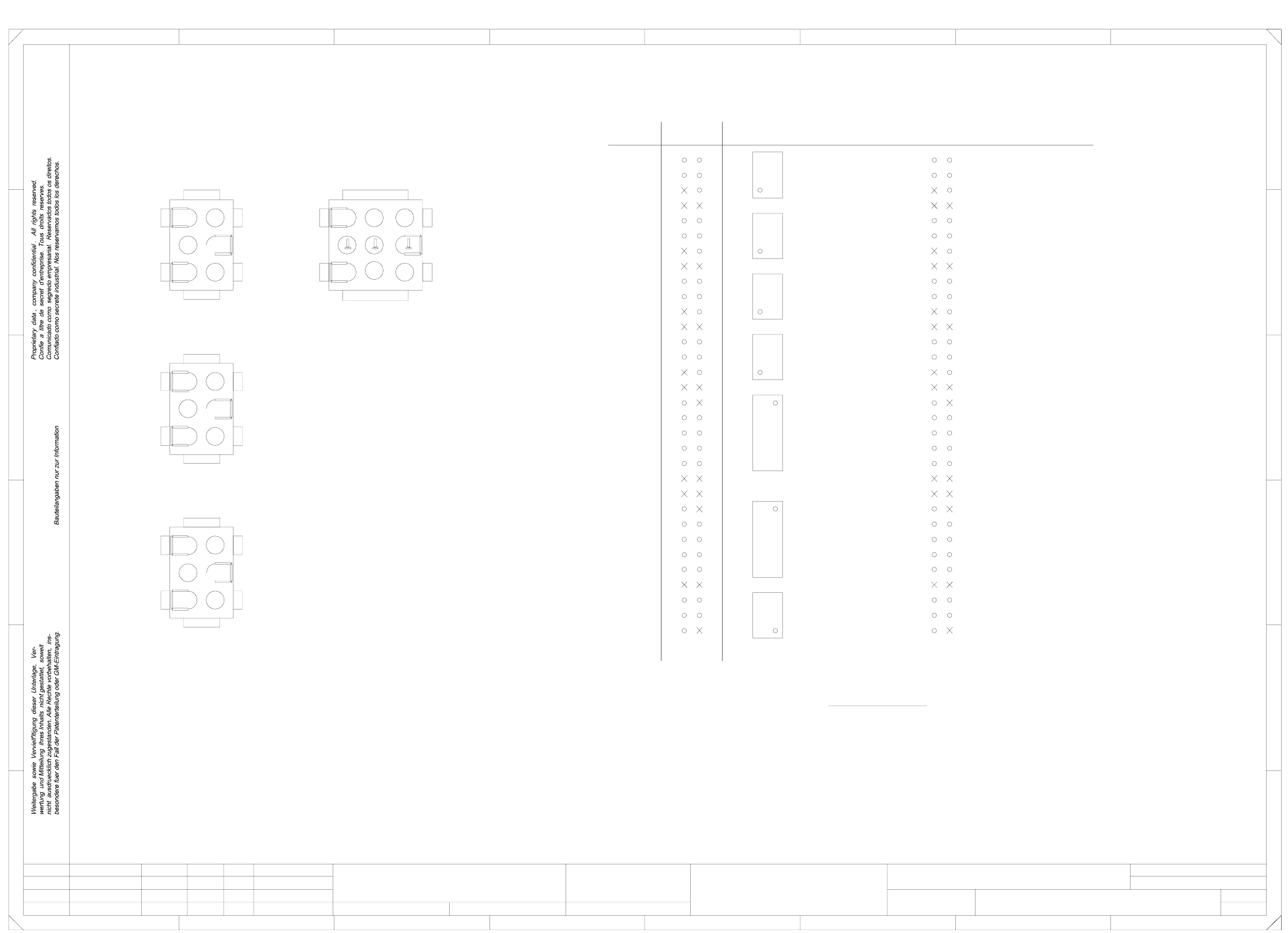
00343907-010102TD3 Servo unit S25, basic module (plug assignment) (Sh. 1 of 3)
=
Datum
Gepr.
Norm
Bearb.
Sheet
Urspr. Ers. f. Ers. d.NameDatumAenderungZustand
SIEMENS AG
+
PL EA1 E
18.11.98
18.09.98
00343907-010102TD3
Servo unit, S23 basic module
#
Tuth
18.09.98
2
10
+24V+15V
T
T
f
2
5
1
5
1
1
9
1
5
14
1L-
+12V
7L+
X3
*
13
X2
X14
X4
X3
8
6
7
4
1L-
*
32
31
1L-
+5V 30
29
28
27
g
key
+5V
-15V
2
6L+ 9
3
26
T
1
72L+
8
1
1
3
SMD-Placement System Siplace S23
Product status
Doc. status
Function status
(plug assignment)
5
5
1
X14
2
10
e
1
9
5
X4
+24V
7L+
key
1L-
6L+
22
19
17
16
15
key
6
a
2
6L+
2L+/5L+
4
5
2
3
12
11
10
9
2
3 6
1
X2
1L+
2L+
1L+
6
3
25
24
23
6
1L+
7L+1+5V
n.u.
Enable-axis
Tacho-
n.u.
4
2
n.u.
Crash prox. sw. 1 X-axis
Crash prox. sw. 2 X-axis
Crash prox. sw. 1 Y-axis
ab
*
*
Crash prox. sw. 1 Y-axis
Crash prox. sw. 2 Y-axis
Crash prox. sw. 1 X-axis
Crash prox. sw. 2 X-axis
T
T
2
6
d
key
*
18
20
21
key
2
b
6
Tacho+
Enable-axis (+15V)
Tacho+
n.u.
key
1
n.u.
Tacho+
n.u.
Enable-axis (+15V)
6
1 4
5
Contact marking
Pin 4-6 jacks 0.5-2.1mm²
Pin contacts 0.5-2.1mm²
Jacks 0.5-2.1mm²
4
5
2
3 6
Pinch off all pins marked 'X'.
+15V +24V
1L+1L+
Enable-axis
Tacho-
Tacho-
Enable-axis
78
A
B
Enable-axis
Tacho-
E
FF
E
Crash prox. sw. 2 Y-axis
Distance sensor
n.u.
n.u.
6
D
C
B
Distance sensor
n.u.
n.u.
n.u.
Distance sensor
'Crash' signal to S5 ->
key
2
6
c
'Crash' signal to S5 ->
n.u.
n.u.
n.u.
n.u.
Enable-axis (+15V)
n.u.
n.u.
Distance sensor
1234
n.u.
n.u.
Tacho+
Jacks 0.5-2.1mm²
Pin 1-3 pin contacts 0.5-2.1mm²
56
Please note !
Pin Anti-crash board
Enable-axis (+15V)
78
12345
C
D
18.09.98
02
01
01
Wer
Leh
Leh
A
n.u.
Sh.
3 Circuit diagrams 80
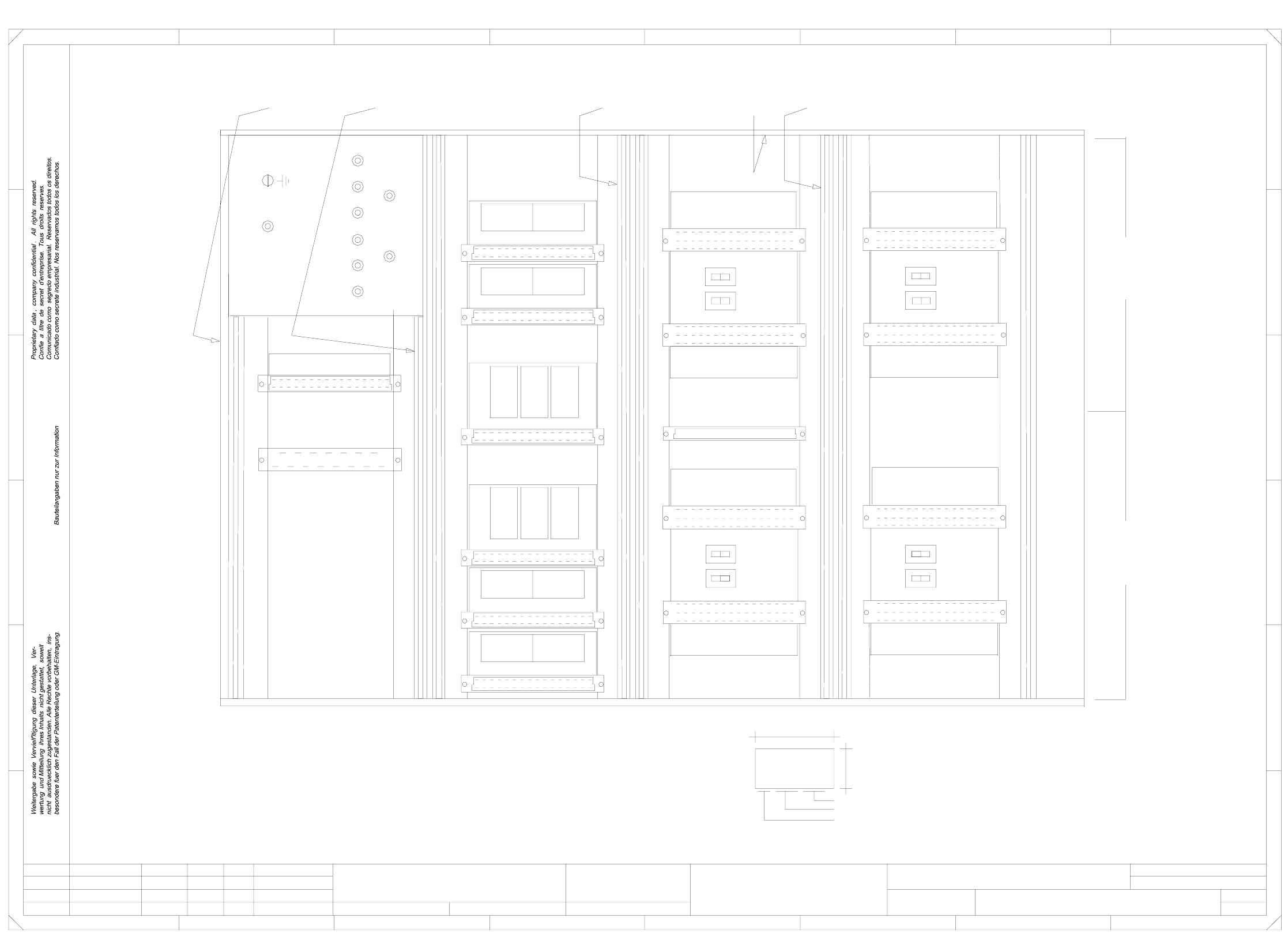
00343907-010102TD3 Servo unit S25, basic module (viewed from the front) (Sh. 2 of 3)
2
3
SMD-Placement System Siplace S23
Product status
Doc. status
Function status
(viewed from the front)
8
10
12
14
16
18
20
22
24
26
Manufacturer/location acc. to SN 37040
4
005
Series number
Date (year/month/day) acc. to SN 01007
tapes according to drawing
20
22
24
26
4
6
001
10
12
40
18
SIEMENS PLEA1
AA-BBBB-CCCC
5V
B: Inspection label Idendification: Testing engineer, month, year
7L+
006
tape A
Inscription
Gantry II
Fan unit A28
12
6
00343907-010101NDI
8
10
12
14
dp1-axis II 'A25'
34
00343907-01
24
26
28
30
32
2
4
A
26
28
30
32
Make and fit inscription
12V
007
2L+
002
16
18
z-axis II 'A26'
22
24
26
C
D
E
S2
X4
18
F
Star II A27'
4
6
8
10
12
14
16
003
E
D
C
B
24
18
22
24
26
28
008
6L+
20
2
4
6
28
30
32
14
16
X3
20
22
A18
A23
2
4
6
8
10
6
16
18
20
22
16
8
* Please note
567
567
A
2L+/5L+
Power supply unit
Dynamic brake Y2-axis
Servo amplifier Y2-axis
A24
dp1-axis I 'A20'
z-axis I 'A21'
Star I 'A22'
32
2
Servo amplifier Y1-axis
A19
2
4
6
8
10
18
28
30
32
2
009
20
28
Ballast X13
S1S1
S1S1
30
32
S2
X4
8
10
12
Inscription
tape C
Inscription
Dynamic brake X1-axis
Servo amplifier X1-axis
tape B
26
28
30
32
S2
12
8
10
12
14
(flush with the front plate):
A: Identification label Assembly inscription acc. to VA-F-510-001
GND
8
X12
Gantry I
X4
X3
Apply the following labels inside
Anti-crash board X11
Dynamic brake X2-axis
Servo amplifier X2-axis
32
14
16
18
20
22
X3
Dynamic brake Y1-axis
02
01
01
Wer
Leh
Leh
S2 = 1
Gantry 2:
12
14
004
24V
1L+
24
26
PL EA1 E
00343907-010102TD3
Servo unit, S23 basic module
#
Tuth
18.09.98
18.11.98
18.09.98
18.09.98
=
Datum
Gepr.
Norm
Bearb.
Sheet
Urspr. Ers. f. Ers. d.NameDatumAenderungZustand
SIEMENS AG
Sh.
+
X3
16
18
20
2
4
30
2
1
2
1
2
14
22
24
6
1
2
1
2
1
2
1
2
1
2
1
Switch settings:
S2 = 2
Gantry 1: S1 = 1
S1 = 2
1234
28
30
8
S2
X4
B
2
tape D
* Note
Inscription
F
3 Circuit diagrams 81
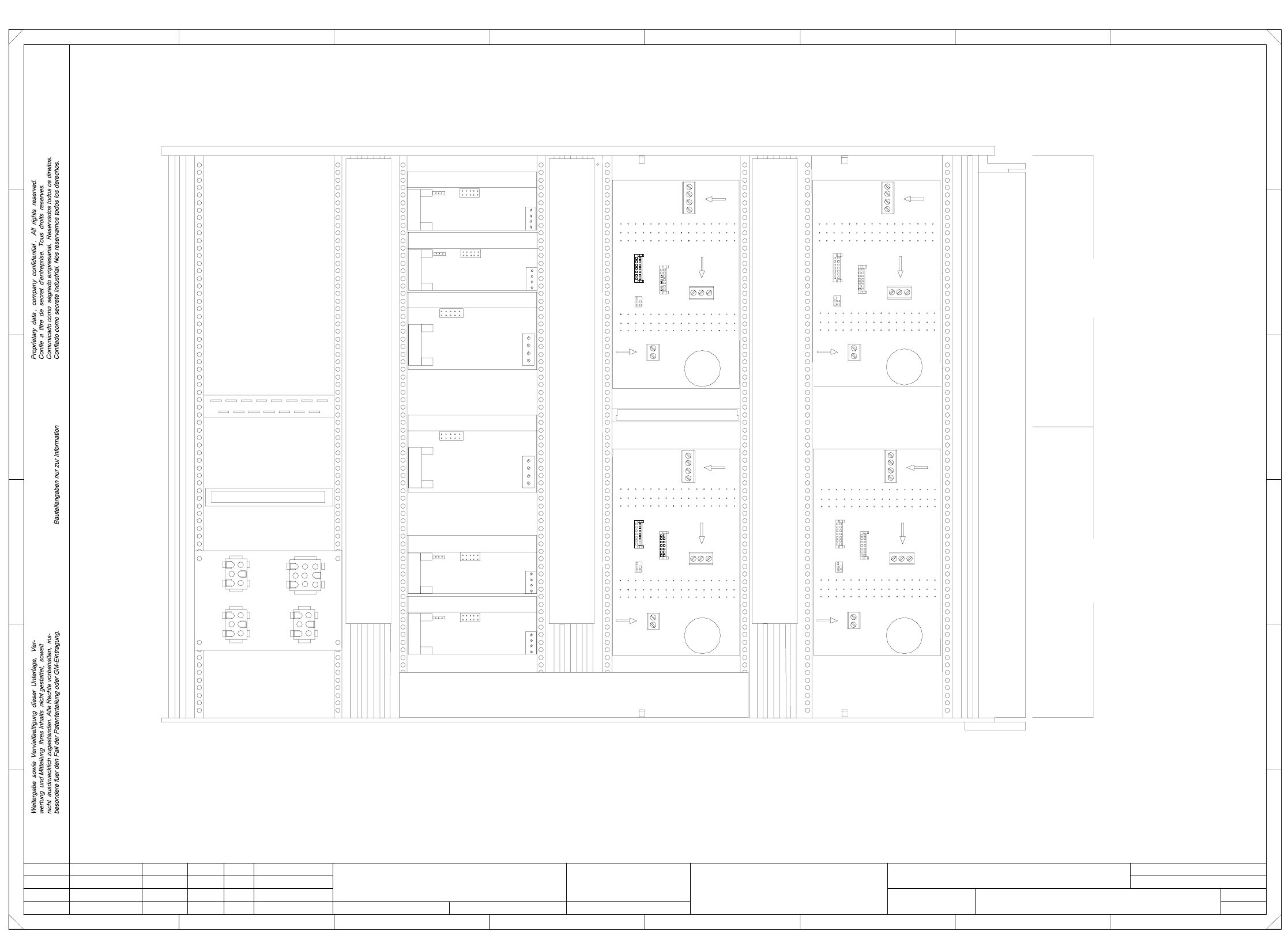
00343907-010102TD3 Servo unit S25, basic module (viewed from the back) (Sh. 3 of 3)
3
3
SMD-Placement System Siplace S23
Product status
Doc. status
Function status
(viewed from the back)
12
Fan unit A28
26
28
30
32
(va)
X8
4
28
X4
X2
X3
z-axis I
A21
2
X3
D
C
4
6
8
10
Star I
12
X1 (vp)
23
Cable duct 001
X1 (vr)
63
Star II
40 645230
E
FF
E
24
X14
X3
15
X3
1
X3
1
X7
32
5
X1 (vc)
X3
55
X2
23
Gantry II
X4
60x30 l=300mm
60x30 l=300mm
60x30 l=300mm
7
41
21
X3
dp1-axis II
Cable duct 002
1
X6
21
1
1
1
A27
32
2
12
14
16
18
12
22
24
34
30
32
(vn)
X8
X4
X3
dp1-axis I
A20
X1 (vf)
71
321
X6
32
14
1
32
20
22
24
26
1
678
1
1
1
45
X1
A24
2
4
8
A
B
C
D
16
18
20
22
A19
26
18
30
8
10
10
Anti-crash board X11
A18
12
20
14
16
18
20
30
32
26
28
6
8
10
12
4
321
X7
24
26
28
30
8
(vb)
1
4
2
4
6
8
10
18
12
X6
21
1
X2
X1
X3 X2
X7
321
6
8
10
12
14
1
X3 X2
X1
3
2
28
21
X7
A26
2
4
6
(vm)
22
24
26
28
30
32
2
4
14
16
30
2
28
30
32
18
20
14
2
4
6
16
10
X8
29
Ballast
X2
30x30 l=250mm
X4
Cable duct 004
8
10
14
16
18
12
X2
X4
A23
2
4
6
C1
C1
C1
C1
X8
22
24
26
X6
21
1
1
3
Leh
Leh
Wer
01
01
02
18.09.98
18.09.98
18.11.98
18.09.98
Tuth
#
Servo unit, S23 basic module
00343907-010102TD3
28
16
18
20
22
32
X13
=
Datum
Gepr.
Norm
Bearb.
Sheet
Urspr. Ers. f. Ers. d.NameDatumAenderungZustand
SIEMENS AG
Sh.
+
PL EA1 E
Cable duct 003
1
64
20
22
B
A
16
4321
22
24
X1 (vo)
X4
X2
A22
X4
18
30
X1 (vd)
20
18
52
Gantry I
6
24
26
A25
Power supply unit
39
X2
X2
X1
X2
X12
14
X3
z-axis II
4
6
8
10