S25 circuit.pdf - 第93页
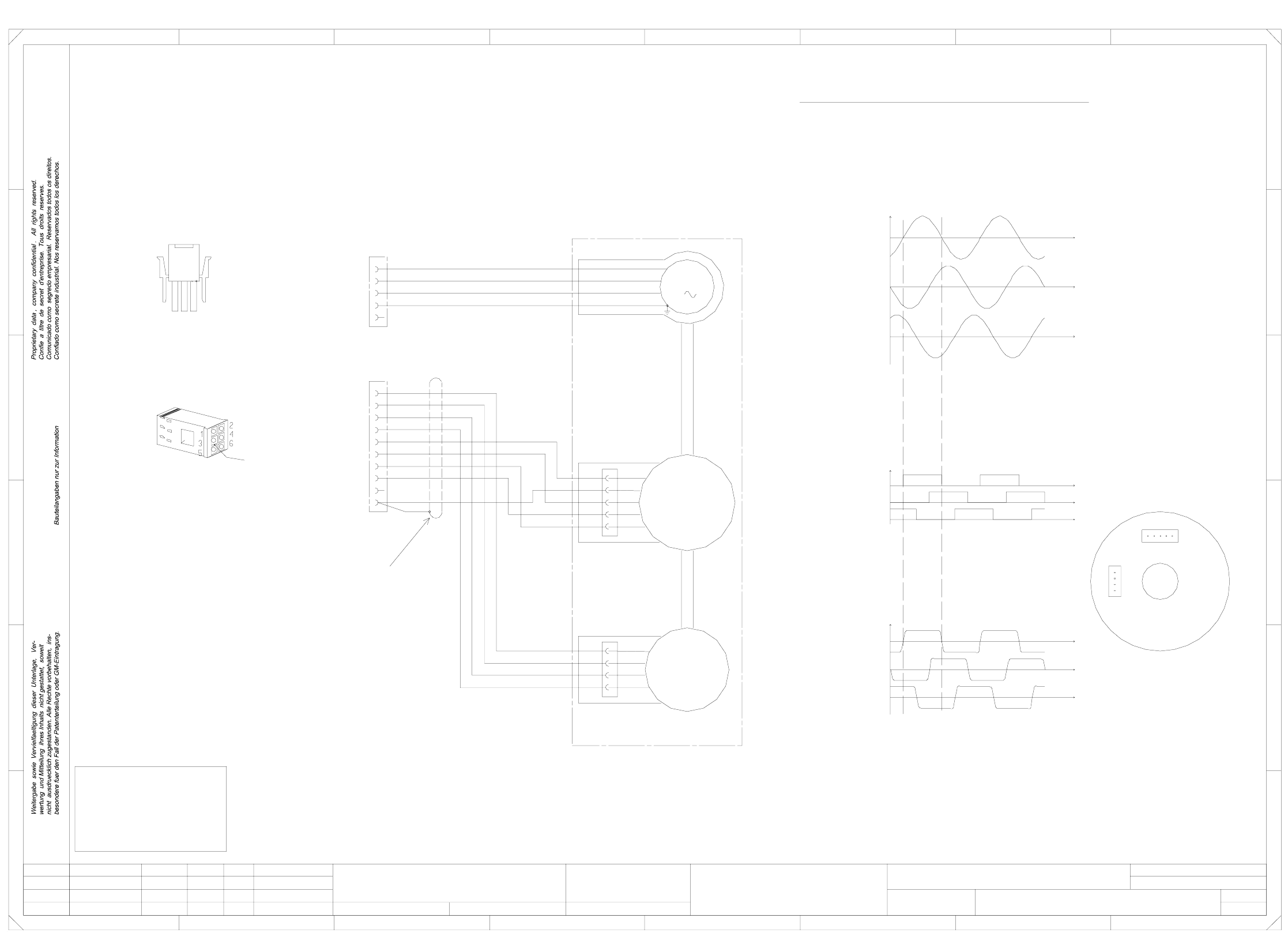
3 Circ uit d iagrams 93 0033706 6-020 102LD3 S25 Y - motor = Dat um Gepr. Norm Bearb. Sheet Urspr. Ers. f. Ers. d. Name Datu m Aend erung Zu sta nd SIEMENS AG Sh. + Tach o U (X 32.1) Mot. W Mot. PE 1 22 33 4y e / g n 5 T…
3 Circuit diagrams 92
00337065-020102LD3 S25 X-motor
1
1
SMD-Placement System Siplace S23
Product status
Doc. status
Function status
for length of the lines and location of the inscription labels.
Refer to drawing 00337065-010102VD3
D
Instructions on the inscription and appearance of the labels
are given in the labeling guidelines for cable sets
specified in the parts list.
1FT3035-6AZ99-9
MATE-N-LOCK
plug casing
3
Connect screen to Pin 10
8
6 wh/br
1
8
bk
2rd
3
RSE U (X13.5)
RSE V (X13.6)
RSE W (X13.7)
Key
10
rd
XR
1
21
1
A
567
M
rd
ye
RSE against RSE (GND) (X13.10)
00337065-02 (W2)
XR
XT
RSE
Tacho
45
8
V (X3.2) to W (X3.3)
Ground at V
test probe at U
U (X3.1) to V (X3.2)
W (X3.3) to U (X3.1)
Calibration of the Tacho/RSE unit for the stator winding
ye/gn
bk
Tacho V (X13.2)
wh
2ye
3gn
4br
5
X13**
67
2
A
B
7 wh/bk
Tacho V
1
Tacho U
or
4
or
vi
wh/br
rd
5
wh/bk
RSE
XT
X motor, S23
#
Werner
21.08.98
12.11.98
18.08.98
18.08.98
02
01
02
Wer
Deu
Deu
PL EA1 E
of the plug, as shown on the label.
The sequence of
numbers is as viewed from the reverse
Cable
00337065-020102LD3
=
Datum
Gepr.
Norm
Bearb.
Sheet
Urspr. Ers. f. Ers. d.NameDatumAenderungZustand
SIEMENS AG
Sh.
+
FOR INFORMATION ONLY !
This document will not
be replaced,
if changes are made!
1
1
Mot. W
Mot. PE
E
F
4
vi
RSE U
RSE V
RSE W
RSE (+5V)
RSE (GND)
9
5
X3**
3
Tacho W (X13.3)
Tacho U (X13.1)
F
E
23
B
C
D
Mot. U
Mot. V
00337065-02 (W1)
All signals are shown by clockwise rotation (looking at the driving shaft)!
Tacho TP
Tacho W
2
ye
4 ye/gn
4
wh
ye
gn
br
Tacho
1
Tacho against TP (X13.4)
3
EMK motor
3
C
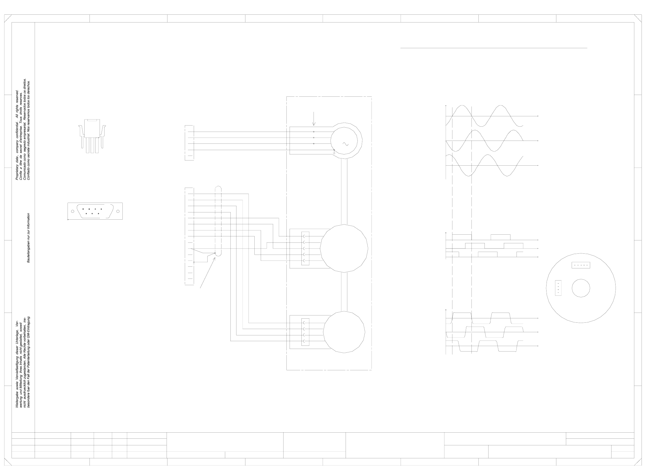
3 Circuit diagrams 93
00337066-020102LD3 S25 Y-motor
=
Datum
Gepr.
Norm
Bearb.
Sheet
Urspr. Ers. f. Ers. d.NameDatumAenderungZustand
SIEMENS AG
Sh.
+
Tacho U (X32.1)
Mot. W
Mot. PE
1
22
33
4ye/gn
5
Tacho U
1
Tacho V
Tacho W
Tacho TP
wh
9ye
2gn
X31*
1
V (X31.2) to W (X31.3)
X32*
11 wh/br
Ground at V
EMK Motor
Calibration of the tacho/RSE unit for the stator winding
RSE U (X32.3)
or
vi
RSE U
RSE V
RSE W
RSE (+5V)
RSE (GND)
1
2
3
4
wh
ye
gn
br
Tacho
1
2
3
4
or
Test probe at U
U (X31.1) to V (X31.2)
W (X31.3) to U (X31.1)
5wh/bk
RSE
RSE V (X32.11)
RSE W (X32.4)
Tacho against TP (X32.10)
Tacho V (X32.9)
Tacho W (X32.2)
or
M
3
1
1
XR
XT
RSE
Tacho
Mot. U
Mot. V
00337066-02 (W1)
00337066-02 (W2)
RSE against RSE (GND) (X32.13)
All signals are shown for clockwise rotation (looking at the driving shaft)!
Connect screen to pin 13,
Key
13
10 br
3
MATE-N-LOK
plug casing
1
4 wh/bk
12 rd
5
234
109
...
C
D
F
E
23
B
3 8
54
vi
wh/br
rd
8
fold back the screen braid
and connect to the plug casing
XT
XR
ye/gn
bk
rd
5 761
1
2
C
D
E
F
4
678
A
B
1FT3046-6AZ99-9
6
14
7
2
3
Crimp connections
SUB-D plug
1
18.08.98
18.08.98
02
01
02
Wer
Deu
Deu
15
via the cable grip.
A
PL EA1 E
00337066-020102LD3
Y motor, S23
#
Werner
21.08.98
12.11.98
1
1
SMD-Placement System Siplace S23
Product status
Doc. status
Function status
Refer to drawing 00337066-010102VD3
for length of the lines and location of the inscription labels.
specified in the parts list.
are given in the labeling guidelines for cable sets
Instructions on the inscription and appearance of the labels
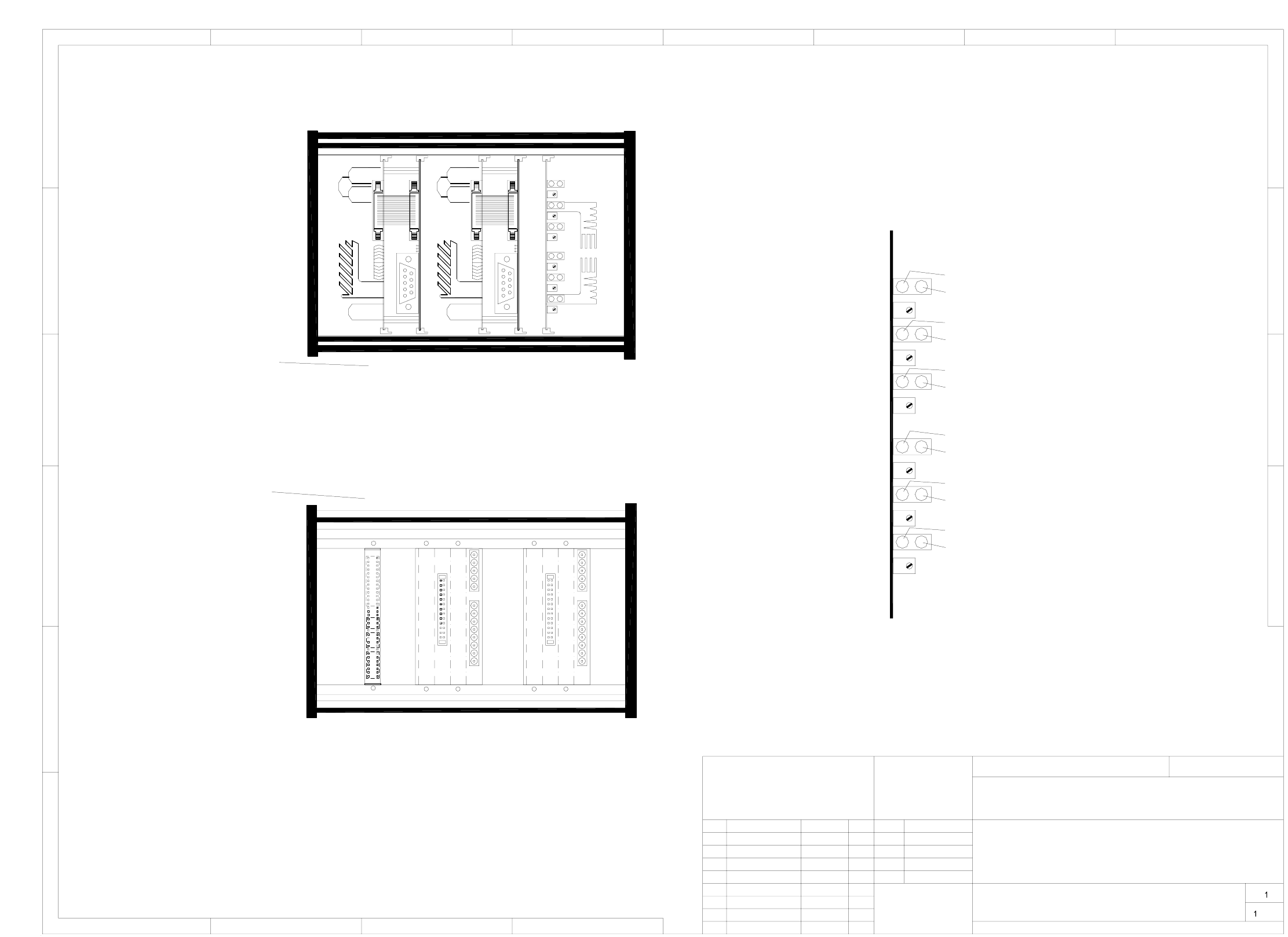
4 OPTIONS circuit diagrams 94
4 OPTIONS circuit diagrams
00327615-020101TD3 Control unit, dual conveyor (viewed from the front/back)
(assemblies overview)
in internally threaded hole no.
X4c X5c X2c
X3c
X3a
X5a
X4a
X3b
X5b
X4b
Half bridge board
Backplane, twin step
motor board, conveyor 1
Backplane, twin step
motor board, conveyor 2
Viewed from the back
module rail hole no.
Board rail in
Viewed from the front
22/2318/1911/12 25/267/8
Twin step motor board, conveyor 2
Twin step motor board, conveyor 1
26 21 17 10 6
Output conveyor 2 fast
Center conveyor 2
Center conveyor 2 slow
Center conveyor 2 fast
Center conveyor 1
Center conveyor 1 slow
Center conveyor 1 fast
Output conveyor 1
Output conveyor 1 slow 1
Output conveyor 1 fast
Input conveyor 1
Output conveyor 1 slow 2
Input conveyor 1 fast
Half bridge board
(viewed from the front/back)
Control unit, dual conveyor
00327615-020101TD3
Mat.-Nr. :
Zust Žnderung Datum Name
Siemens AG
Beab.
Datum
Gepr.
Norm
Massstab
Bl.
Bl.
1
1
243
2345678
A
B
C
D
E
F
A
B
C
D
AUT5-BSM
CAD-Datei:
SMD-Placement System Siplace 80S20
Function status
Doc. status
Product status
Multipole connector / backplane
of module rail.
Half bridge board
26.06.1996
Dietel
1.
Wer
Wer
2.
14.05.97
14.05.97
1.
14.05.97
Wer
80S20/DCTA/
32761521_d
(assemblies overview)
Input conveyor 2
Output conveyor 2 slow 2
Input conveyor 2 fast
Output conveyor 2
Output conveyor 2 slow 1