4OM-1075-002.pdf - 第19页
Fig. 4A6 Front View of Machine 1.3 Maintenance Spots 0206-003 1-6 AHB01ETRP
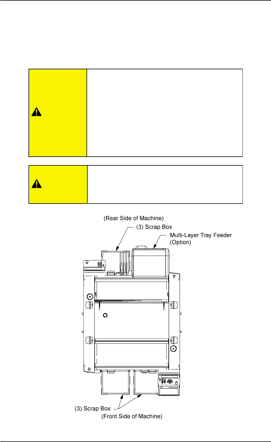
1.3 Maintenance Spots
1.3.1 General View
Refer to "1.3.2" and the subsequent items for details.
• Before performing maintenance work, turn off the
power and air sources and lock the power breaker
using the padlock.
• Designate a person who can have charge of the
padlock key.
• Any operations with a cover(s) being removed are
included.
After the maintenance work, be sure to attach the
cover.
• As for the options such as a multi-layer tray feeder,
refer to each instruction manual of the specially
specified devices for the maintenance.
Fig. 4A5 Top View of Machine
1.3 Maintenance Spots
0308-004 1-5 AHB01ETRP
CAUTION
CAUTION
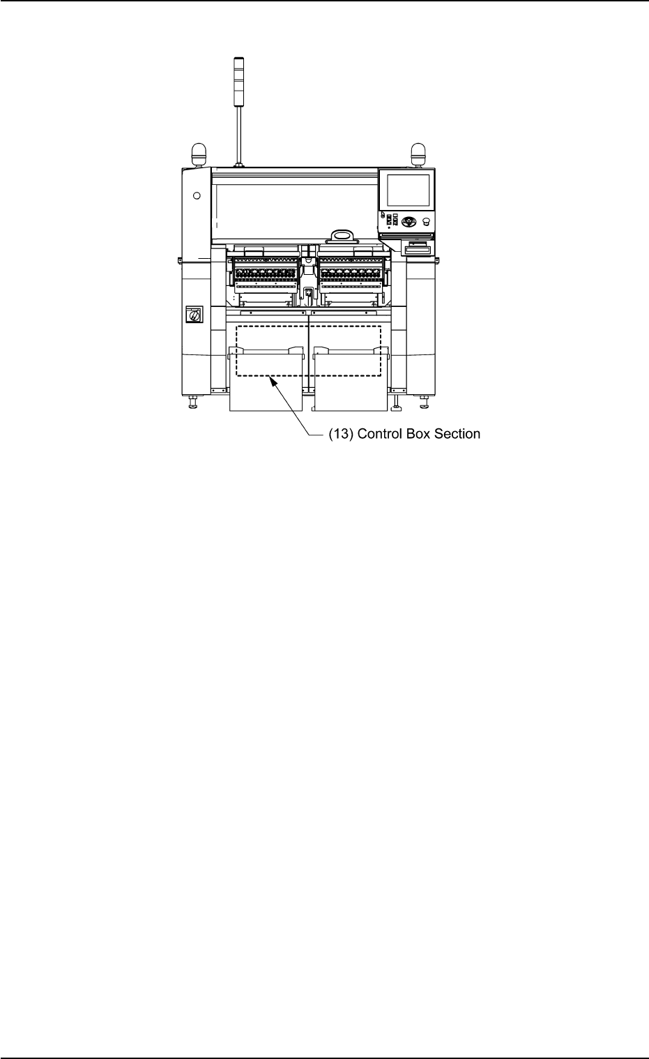
Fig. 4A6 Front View of Machine
1.3 Maintenance Spots
0206-003 1-6 AHB01ETRP
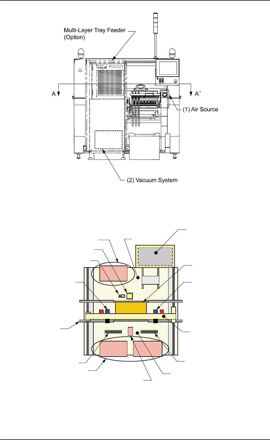
Fig. 4A7 Rear View of Machine
Fig. 4A8 Sectional View A-A’
1.3 Maintenance Spots
Multi-Layer Tray Feeder #2
(Option)
(5) Feeder Base
(8) Fixed Camera Section
(7) Teaching Plate Section
(9) Head Section
(11) Conveyor Section
(12) Nozzle Stocker Section
(5) Feeder Base
(4) Component Storage Box
(14) Frame
(12) Nozzle Stocker Section
(10) X/Y Beam Section
(9) Head Section
(6) P.C.B. Positioning Section
(P Conveyor)
(14) Frame
0206-003 1-7 AHB01ETRP