4OM-1075-002.pdf - 第48页
0206-003 1-34 AHB01ETRP 1.4 Maintenance Method • Adjustment Procedure (1) T urn on the power supply . (2) Open the safety door and set the [OPERA TION] switch to the "SETUP" side. T urn off the [READY] button. …
0308-004 1-33 AHB01ETRP
1.4 Maintenance Method
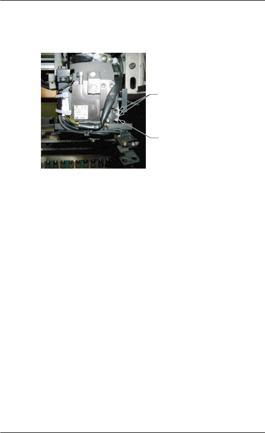
(4) Move down the NC-axis cam origin sensor.
Remove two Bolts B with a hex-head wrench (2 mm) and detach
the nozzle change cam.
Fig. 4A41
••
••
• Attachment Procedure
(1) Attach a new nozzle change cam with two Bolts B.
(2) Fasten the NC-axis cam origin sensor plate by temporarily tighten-
ing two Bolts A and arrange the cables with two tie wraps.
(3) Lubricate the nozzle change cam.
Wipe off old grease with a rag and apply a small amount of new
grease with a cotton swab, etc.
Bolts B
(2 pcs.)
Nozzle Change Cam
(Part No.: 630 094 1692)
0206-003 1-34 AHB01ETRP
1.4 Maintenance Method
• Adjustment Procedure
(1) Turn on the power supply.
(2) Open the safety door and set the [OPERATION] switch to the
"SETUP" side.
Turn off the [READY] button.
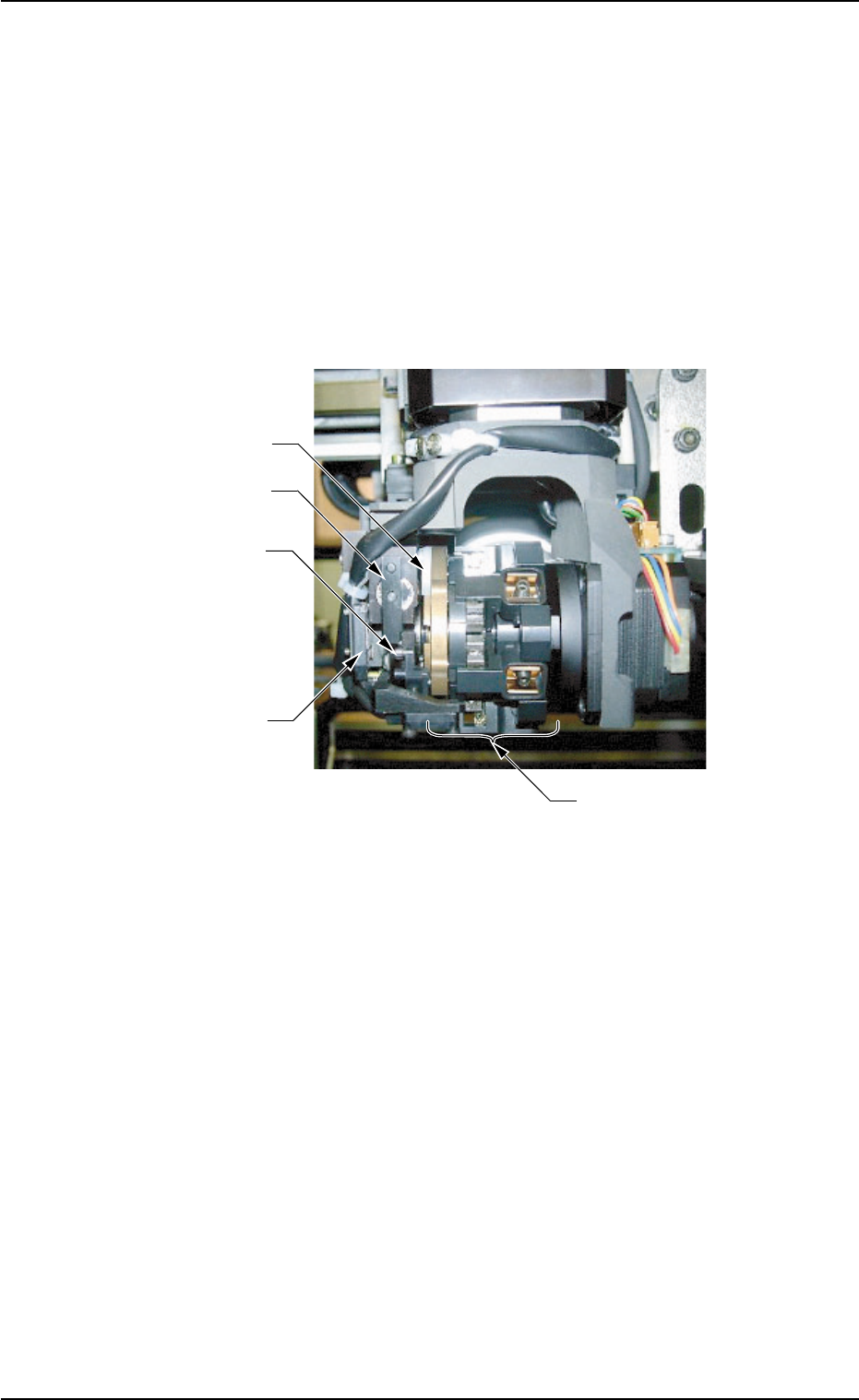
(3) Rotate the nozzle clamping section such that the nozzle change
cam is located at the upper side.
Fig. 4A42
Nozzle Change
Cam
Clutch Lever
Clutch Pin
NC-Axis Cam Origin
Sensor
Nozzle Clamp Section
0308-002 1-35 AHB01ETRP
1.4 Maintenance Method
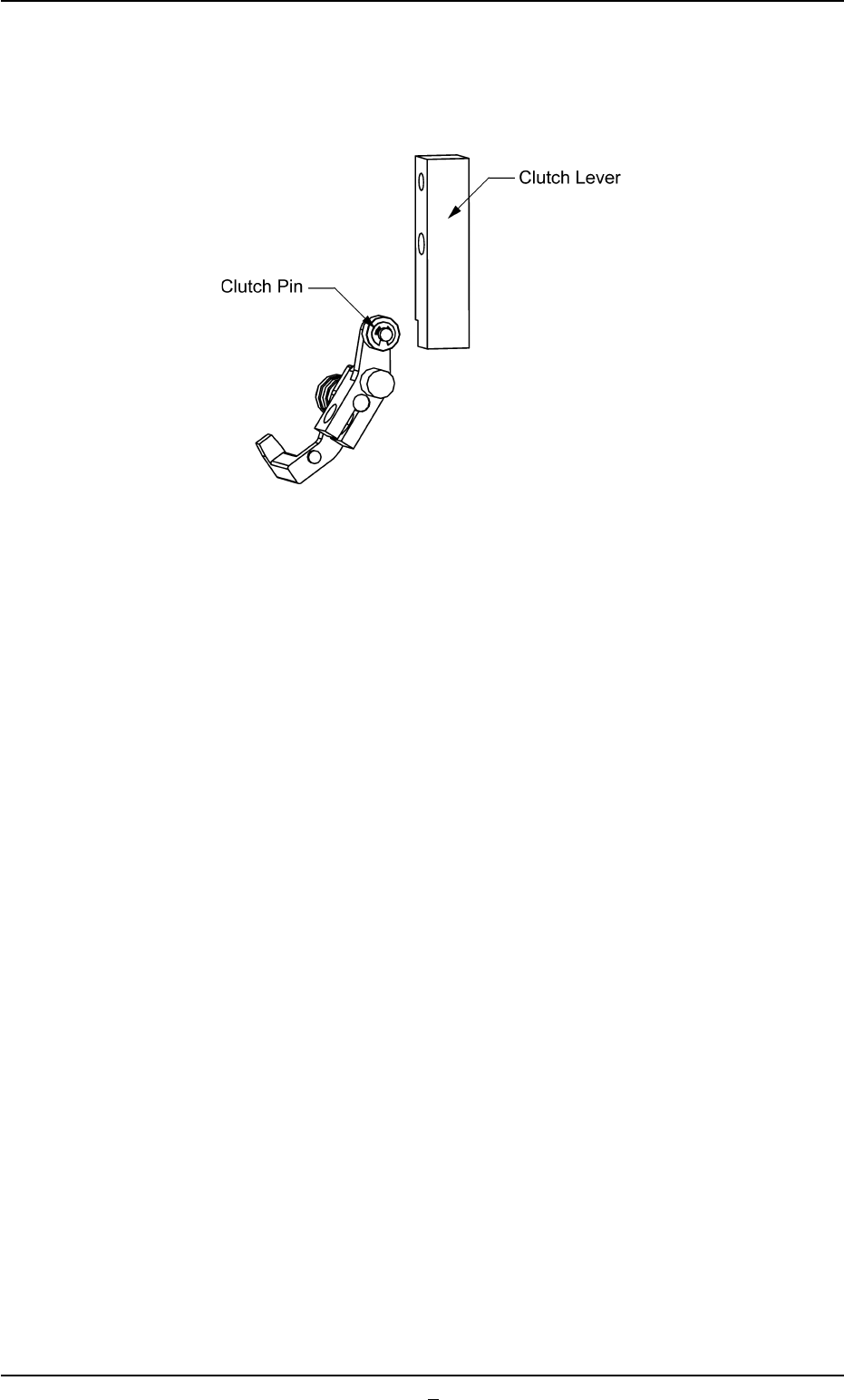
(4) Adjust the NC-axis cam origin sensor plate such that the sensor is
turned on with the end of the clutch pin located at the edge of the
cutout area of the clutch lever.
Fig. 4A43
(5) After the position is determined, tighten two Bolts A securely.
(6) Open the "Zeroing Opn." tab sheet and perform the zeroing opera-
tion for all devices. (Operation Sequence: [MAINT.] Button Æ [MNL
OPN.] Button Æ "Zeroing Opn." Tab)
(7) Open the "Nozzle Change" tab sheet. (Operation Sequence: [MAINT.]
Button Æ [UNIT ADJ.] Button Æ "Nozzle Change" Tab)
Make nozzle selections and check for errors.