4OM-1075-002.pdf - 第93页
3. T roubleshooting after "ERROR" Window (Error ID) Assuming "Error ID", "Item (Error Name)", and "Description" in the "ER- ROR" window as an index, the system retrieves …
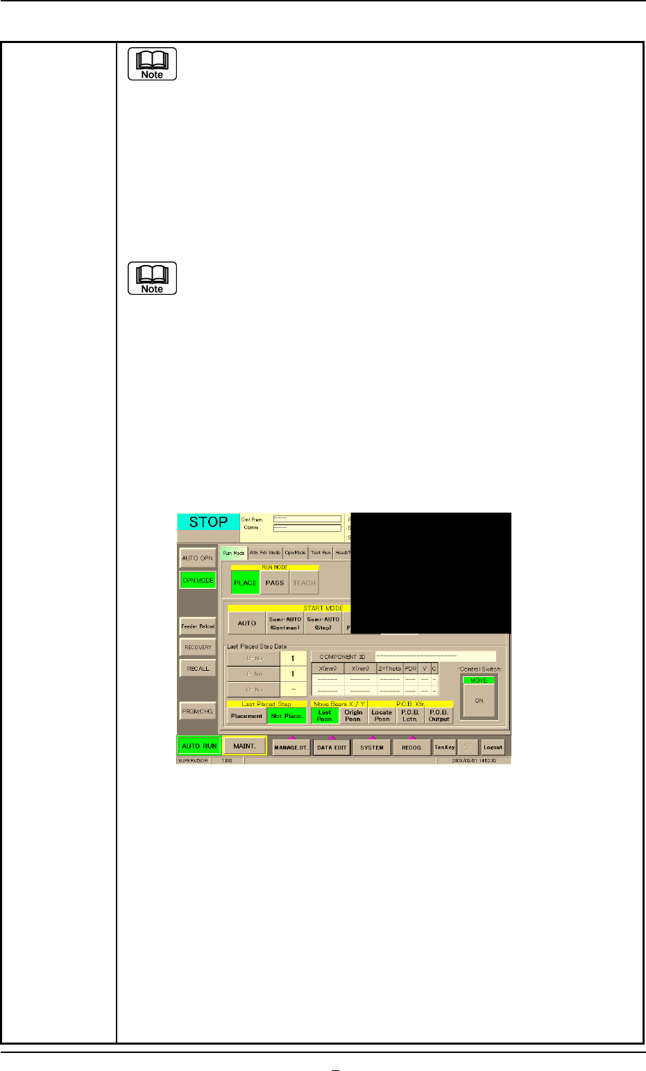
Table 4B3-6
(a) When the "Warm Start" operation is feasible, the [WARM] button
appears in the "OPN. MODE" window (submenu).
(b) When the [WARM] button is not displayed, it means that the "Warm
Start" operation is not feasible or there was a mistake in the re-
medial procedure after an error had occurred. In this case, per-
form the semi-automatic operation (step designation) to reset the
machine to its normal condition.
(8) Check how the last component was placed when the operation was inter-
rupted.
The last placement step is indicated in the "
Last Placed Step Data"
group box in the "OPN. MODE" window (submenu).
Check visually whether or not the relevant component is placed on
the P.C.B.
(9) Press the [Last Placed Pos.] button (entitled "Move Beam X/Y" in the "OPN.
MODE" window (submenu).
(10) Press the [RECOG.] button on the main menu bar and make the recog-
nition window (1/4 of the whole view at the upper right corner) appear.
(11) Press the [ON] button (entitled "MOVE"). In two seconds, press the [EN-
ABLE] button on the operation panel.
The last placement position is displayed as a recognition image.
Fig. 4B14 "OPN. MODE" Window (Last Step Confirmation)
(12) Check whether or not the component is placed. If not, select the [Place-
ment] button. If the component is already placed, select the [Not Place-
ment] button.
(13) Press the [ENABLE] button on the operation panel in 2 seconds after
the [Origin Pos.] and the [ON] button (entitled "MOVE").
The XY beam returns to its origin.
(14) Press the [START] button on the operation panel. The "Warm Start"
operation is implemented.
(15) As for the P.C.B. produced through "Warm Start" operations, be sure to
confirm that all components are correctly placed.
2.4 Continuous Operation Disabled during Component Placement
0308-002 2-8-6 AHB01ETRP
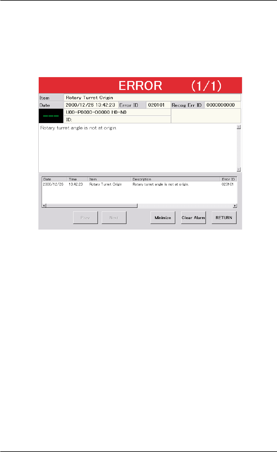
3. Troubleshooting after "ERROR" Window (Error ID)
Assuming "Error ID", "Item (Error Name)", and "Description" in the "ER-
ROR" window as an index, the system retrieves the related page of the
instruction manual.
Refer to "3.1 Typical Description" for the detailed description.
Fig. 4B15 Example of "ERROR" Window
3. Troubleshooting after "ERROR" Window (Error ID)
0206-002 2-9 AHB01ETRP
3.1 Typical Description
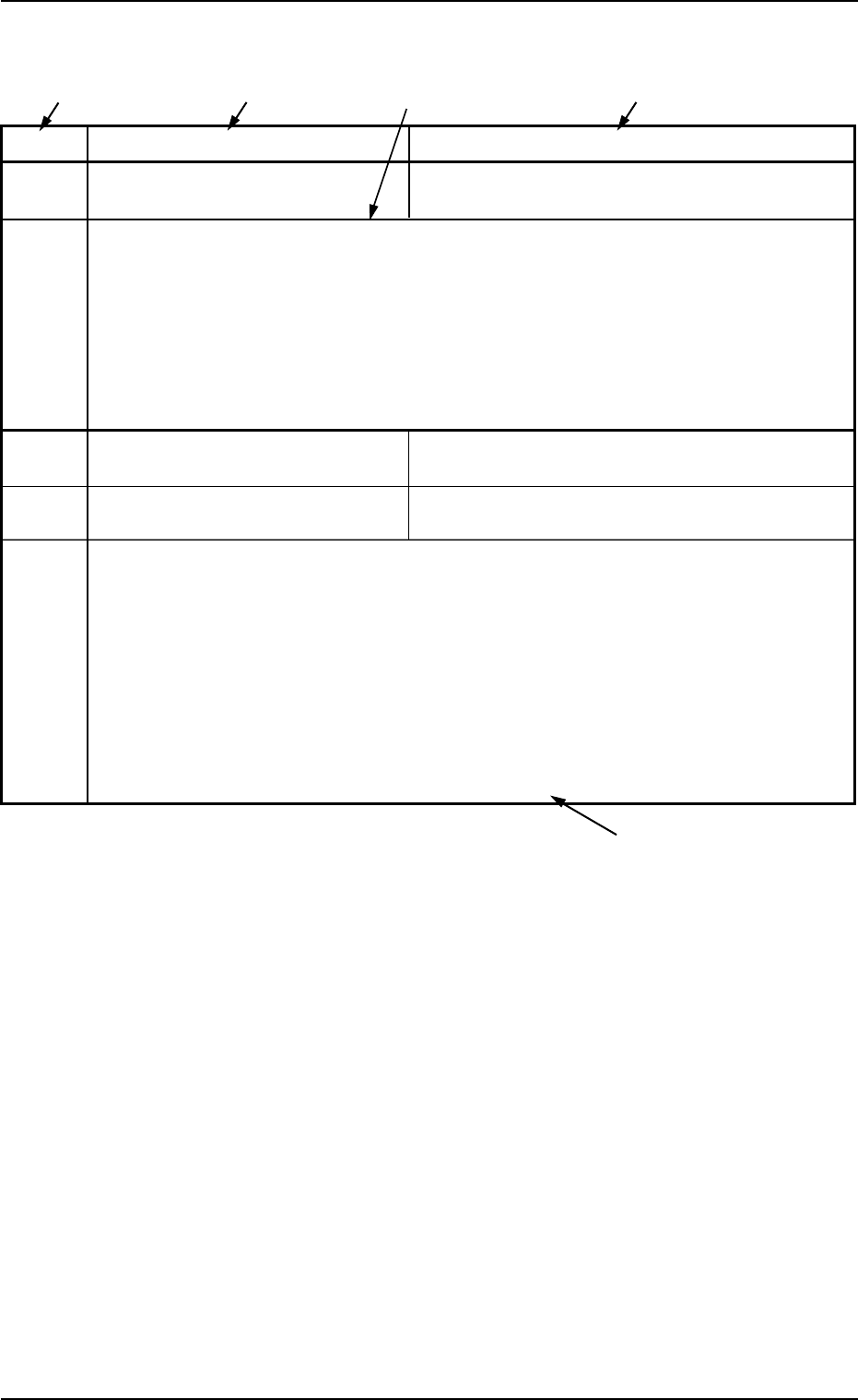
Table 4B4
Error ID Item Description
050301 Y2 Axis Data The driver data was detected outside of the possible
range.
(Cause 1) Self-Diagnostics Error Message
(Remedy 1) Zero all axes and re-start the operation.
When the machine cannot be set to its normal condition, consult our service
personnel for the remedy.
050401 Y2 Axis Limit (+) Limit error has been detected.
050402 Y2 Axis Limit (-) Limit error has been detected.
(Cause 1) The X1 axis might have overrun due to generation of noises, overcurrent, etc.
The sensor may be defective.
(Remedy 1) Zero all axes and re-start the operation.
When the machine cannot be set to its normal condition, consult our service
personnel for the remedy.
(Continued to the next page)
*1 The error IDs (IDs displayed in the "ERROR" window) are described
in the numerical order.
*2 Described are the error name (item) and the description in the "ER-
ROR" window.
*3 Described are the causes and remedial procedures of the errors
(Item and Description).
The causes and remedies are correlated as follows.
(Cause 1)
ÆÆ
ÆÆ
Æ (Remedy 1)
(Cause 2)
ÆÆ
ÆÆ
Æ (Remedy 2)
(Cause 3)
ÆÆ
ÆÆ
Æ (Remedy 3)
*4 This indicates that the related contents are described subsequently
on the next page.
*4
*2
*3
*2
*1
3.1 Typical Description
0107-001 2-10 AHB01ETRP