YesAX V3.1.2 - Software User Manual - 第105页
General Inspecti on Methodolo gy 10 - 11 10.3.1 Edit Lead Ban k Parameters Select Edit Lead Bank Par ams.. from the Lead Bank pop-up menu to open the Edit Lead Ba nk Parameters dialog. Set the pitch of the lead, the numb…
10-10 General Inspection Methodology
The Edge Threshold defines the minimum edges strength. Edge strength ranges from 0 to 100.
The Expected Width set the expected width of a strip.
The Positional, Rotational and Width Tolerances define the tolerance for the position, angle
and width.
The default angle is 0 degree. If user enables Use Expected Angle and set a number for the
desired angle, software will use this as default angle instead of 0 degree.
10.3 Lead Bank Inspection
Lead Bank inspection checks for leads of IC components as well as solder balls of BGA
components. The default algorithm for lead bank inspection of IC components is Blob analysis.
The default algorithm for lead bank inspection of BGA components is BGA Group (see 10.5.2
Lead Bank Inspection). The default algorithm for bond wire inspection of bond wire components
is Bond Wire Sweep analysis.
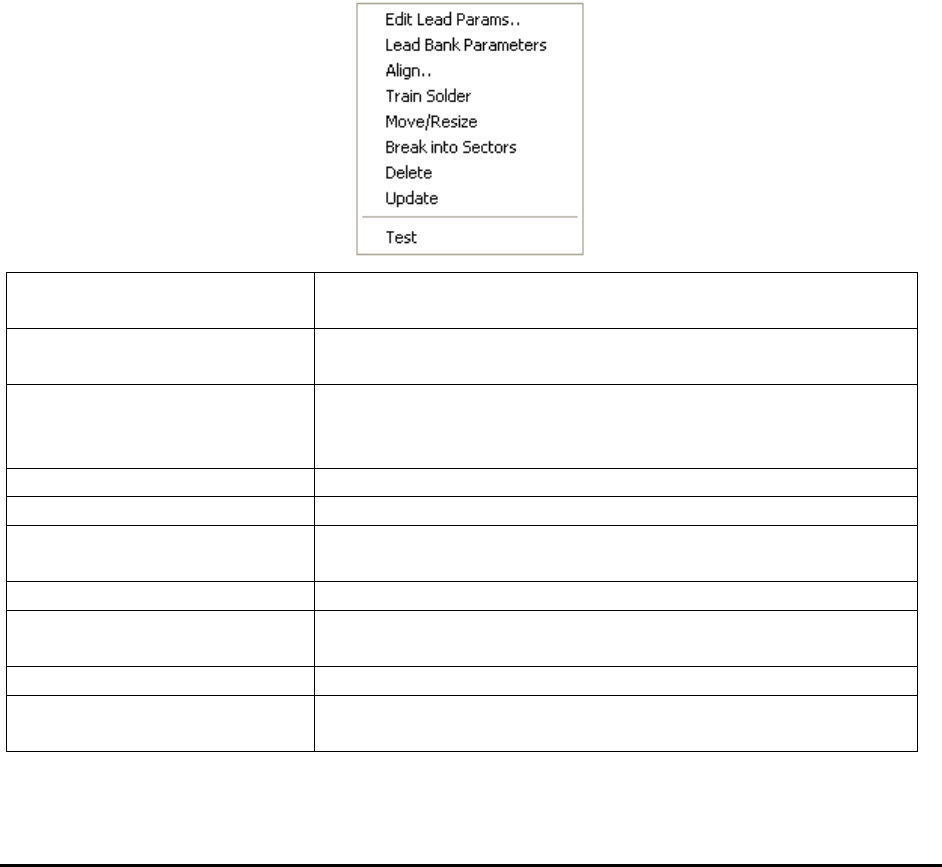
After a lead bank inspection box is created, display the Lead Bank pop-up menu by pressing the
right mouse button while pointing at the inspection box.
Edit Lead Params..
Launches the Lead Bank Parameters dialog. See 10.3.1 Edit
Lead Bank Parameters.
Lead Bank Parameters
Launches the Lead Blob Analysis Parameter dialog. See
10.3.2 Lead Blob Analysis Parameter
Align..
Launches the Lead Bank Alignment dialog to allow
alignment of the lead bank inspection box. See 10.3.3 Lead
Bank Alignment.
Train Solder
Trains the solder inspection within the lead bank.
Move/Resize
Moves or resizes the lead bank inspection box.
Break into Sectors
Breaks up a long lead bank into smaller sectors. See 10.3.4
Break Lead Bank into Sectors.
Delete
Deletes the inspection box.
Update
Uses the current lead bank as reference to update the
parameters of other lead banks. See 10.3.5 Update Lead
Test
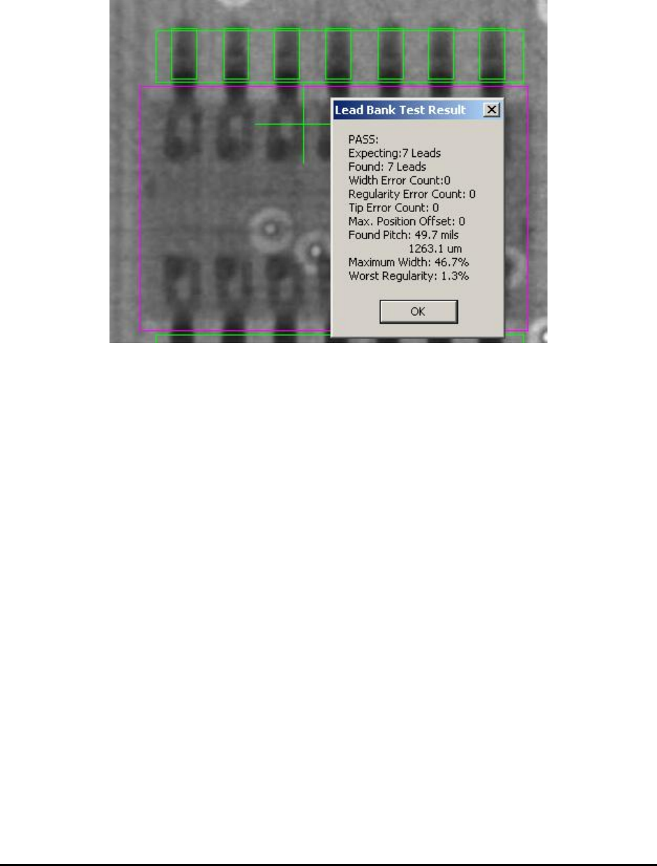
Tests the lead bank inspection on the current image.
Bond Wire Params..
Launches the Bond Wire Sweep Parameters dialog. See
10.3.6 Bond Wire Params..
General Inspection Methodology 10-11
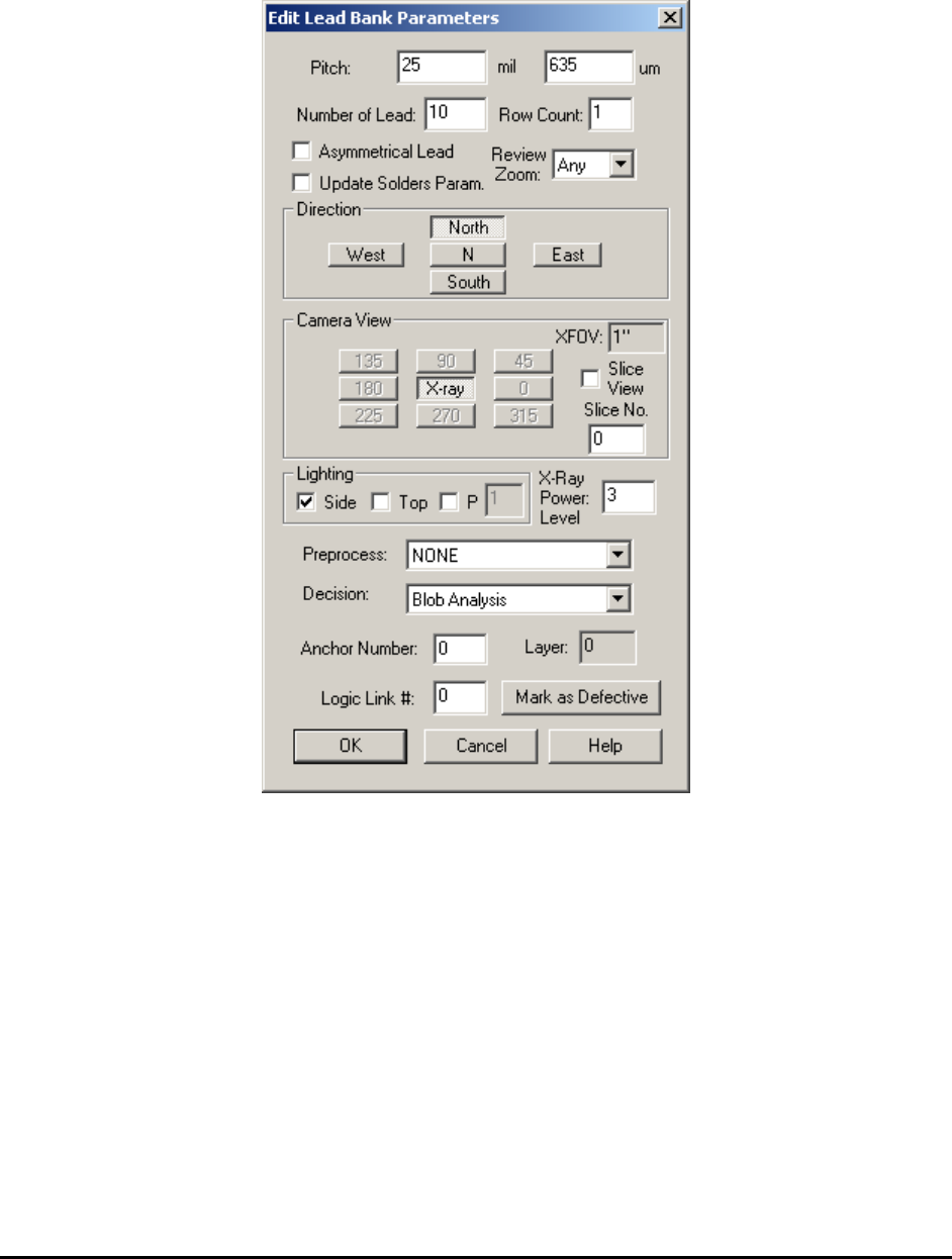
10.3.1 Edit Lead Bank Parameters
Select Edit Lead Bank Params.. from the Lead Bank pop-up menu to open the Edit Lead Bank
Parameters dialog.
Set the pitch of the lead, the number of leads in the lead bank, the direction, the view, the
lighting and the algorithm selection.
The Asymmetrical Lead checkbox should be checked if the lead arrangement for the part is not
symmetrical. For example on SOT-25 parts there are two leads on one side but three on the
opposite.
The Update Solders Param. Checkbox will allow the same settings (Direction, XFOV, Lighting
and XPL) which the current lead bank uses apply to all solders within the lead bank, if checked
by user.
The Row Count should always be 1 for all the normal components. Multiple rows of leads per
side is for pin array inspection or BGA solder ball or solder paste inspection only.
The Review Zoom list box selects the preferred zoom level for reviewing this lead area during
the defect review process.
10-12 General Inspection Methodology
Lead bands can be anchored by a marking for precise positioning. See 14.4 Anchor Block
Fiducial and Local Fiducial for details.
The X-ray Power Level specifies the current power level for lead inspection.
10.3.2 Lead Blob Analysis Parameter
Select Lead Bank Parameters from the Lead Bank pop-up menu to open the Lead Lob Analysis
Parameters dialog.