YesAX V3.1.2 - Software User Manual - 第113页
General Inspecti on Methodolo gy 10 - 19 Select Percent Void Params from the Solder pop-up menu to open the Percent Void Parameters dialog.
10-18 General Inspection Methodology
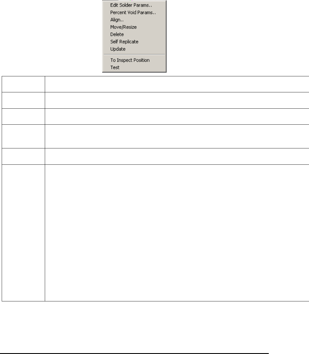
After the solder inspection box is created, you can display the solder pop-up menu by
pressing the right mouse button while pointing inside the solder inspection box.
Edit Solder
Params..
Launches the Solder Parameters dialog. See 10.4.1 Edit Solder Parameters.
Histogram
Setup
Launches the Histogram Parameters dialog. See 10.4.2 Histogram Parameters.
Pat Match
Param..
Launches the Pattern Matching Parameter dialog. See 10.4.3 Pattern Matching Parameters.
X-ray
Solder
Setup
Launches the X-ray Solder Parameters dialog. See 10.4.4 X-Ray Solder Parameters.
Solder Blob
Params
Launches the Solder Blob Analysis Parameters dialog. See 10.4.5 Solder Blob Analysis
Parameters.
Align..
Launches the Solder Alignment dialog for the user to align the solder inspection boxes. See
10.4.6 Percent Void Parameters
The Percent Void inspection enables measurement of the number of pixels and the percentage of
pixels in a user selected window within a defined gray scale range. The Percent Void function is
designed primarily for semiconductor applications such as measuring an area of a device which
may show some bonding inconsistencies, bonding voids, solder voids, air gaps and provide the
user with a percentage of the area that may be affected. The percent void measurement can be
applied to many other measurements where an area defect or point of interest is concerned.
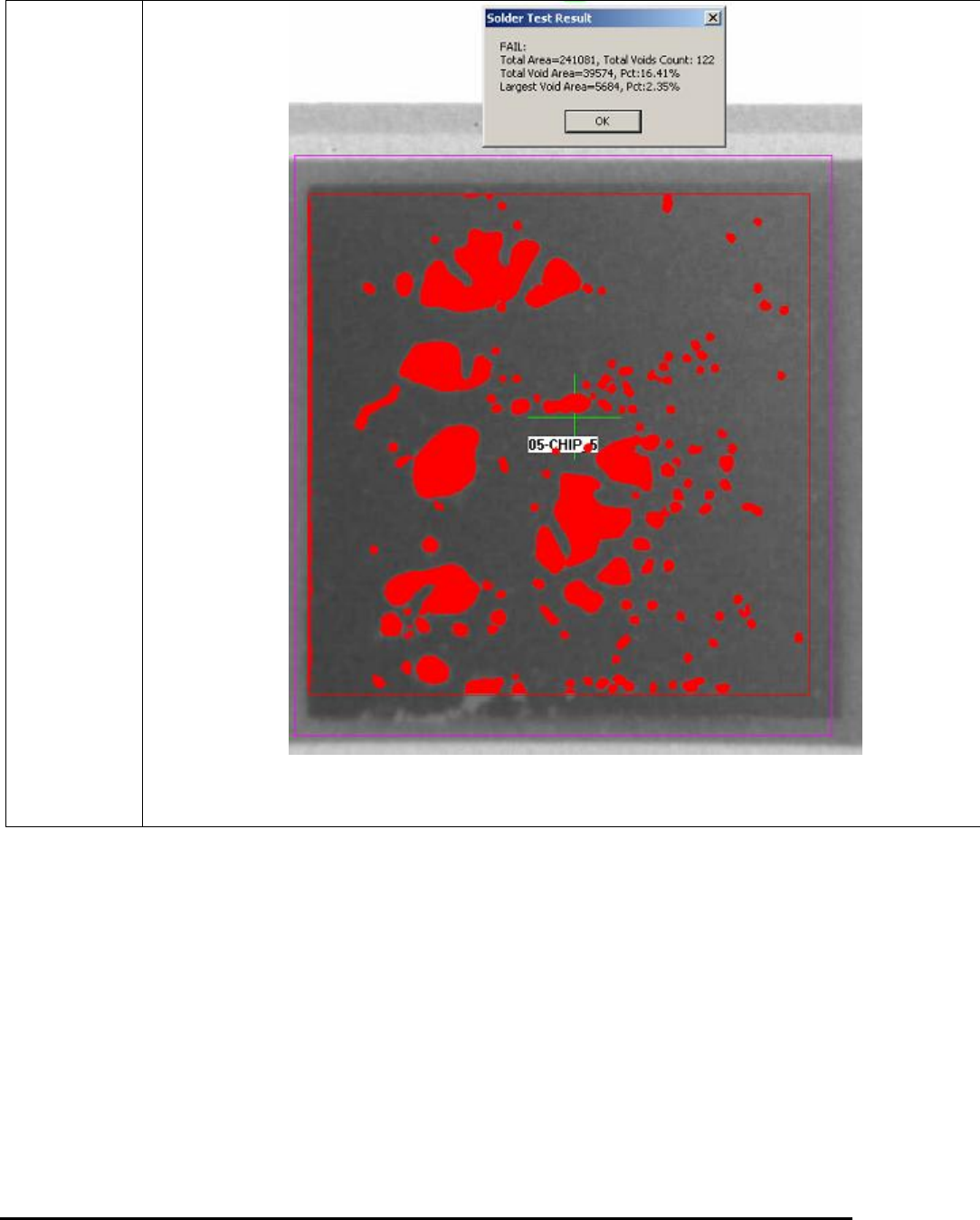
The function computes the total number of pixels, the number of highlighted, “lit”, pixels and the
number of pixels in the largest lit blob within the windowed area. It determines the percentage of
lit pixels and the percentage of pixels in the largest lit blob, and then compares them with the
pass/fail thresholds set in the Max Void and the Largest Void fields. If either percentage is more
than its threshold, the system reports that Percent Void failed; otherwise, it is reported to have
passed.
The Percent Void result is presented in the Solder Test Result dialog box as shown below. By
default the void area been detected will be shown in red.
General Inspection Methodology 10-19
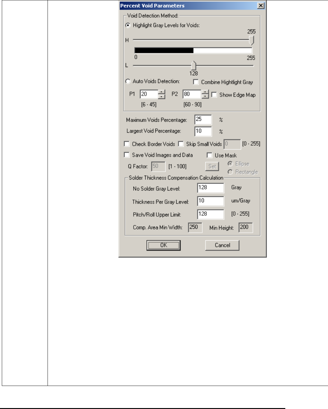
Select Percent Void Params from the Solder pop-up menu to open the Percent Void Parameters
dialog.
10-20 General Inspection Methodology
The Highlight Gray Levels for Voids enables the user to highlight a range of gray scale values
that include the feature of interest. These highlighted pixels will be considered “lit” during the
Percent Void computation.
The Auto Voids Detection applies edge detection techniques to find voids. There are two
parameters for this function: P1 and P2. P1 is the indicator for a Gaussian Median filter and P2
represents one high threshold value. The normal range for P1 is from 6 to 45 and the range for
P2 is from 60 to 90, as shown under each box. For most applications you may set P1 somewhere
between 12 and 24 and set P2 between 70 and 80. The default values for P1 and P2 are 20 and
75, correspondingly.
To adjust these two parameters, you should always start with P1 and pay more attention on this
one since this is the one that affects final result more. Increasing the value of either P1 or P2, you
tend to lose small voids and in the mean time, get rid of un-wanted noise. Try not use very low
value for P1 when image noise level is high. Also be noticed that increasing P2 too much may
break the contour line of some voids and create some irregular shapes. To help tuning P1 and P2,