YesAX V3.1.2 - Software User Manual - 第126页
10 - 32 General Inspecti on Methodolo gy 10.4.7 Solder Alignment Using this dialog the user can move and size the solder inspection boxes. Select Align.. from the Solder pop-up menu to open the Solder Alignment dialog. T…
General Inspection Methodology 10-31
The Solder Thickness Compensation Calculation is for solder thickness compensation purpose.
It won’t be enabled if the following two fields: No Solder Gray Level and High Pitch/Roll
Threshold are filled with 0 or the solder inspection box has a width less than Comp. Area Min
Width (250 in pixels) or a height less than Min Height (200 in pixels). In reality the solder
thickness of a solder joint is not even. For example, if the component is tilted in one way, then
along that direction the thickness of the solder area will gradually increase or decrease, which
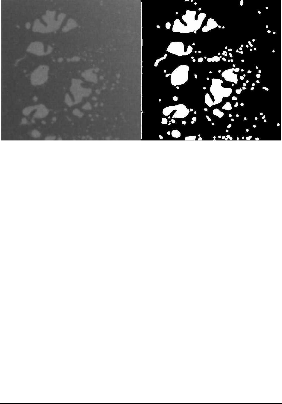
causes the unevenness of the image. If a void is located at relatively thick solder area, it may
even appears darker than some thin solder areas without any void at all. This will make void
detection more difficult. The solder thickness calculation is designed to compensate for the
unevenness of the solder layer.
To make it work, first the user needs to set up the No Solder Gray Level, which represents the
average gray levels for areas without any solder. To set up Thickness Per Gray Level, some
calculation needs to be done first. If the thickness of solder is 500µm (this number can be
acquired by doing laser height measurement on solder area), and the gray levels for such amount
of solder is 50, then the Thickness Per Gray Level will be 10µm/Gray (500/50). Once the pitch
and roll have been calculated, the results will be compared with High Pitch/Roll Threshold first.
Only numbers bigger than the preset threshold value will be used for thickness compensation. If
the numbers are smaller, it is reasonable to assume that the numbers are not reliable thus the user
will choose rather not doing the compensation at all. The results of Pitch and Roll can be seen on
the percent void result dialog, together with the inspection results.
Sometime there is certain area inside the ROI that the user does not want to inspect. To mask out
the area the user can enable the Use Mask option, select either Ellipse or Rectangle as shape
indicator and then click Set button to define the mask area. The mask area does not need to be
totally reside inside the ROI and the mask out area will be subtracted from the total area
calculate.
10-32 General Inspection Methodology
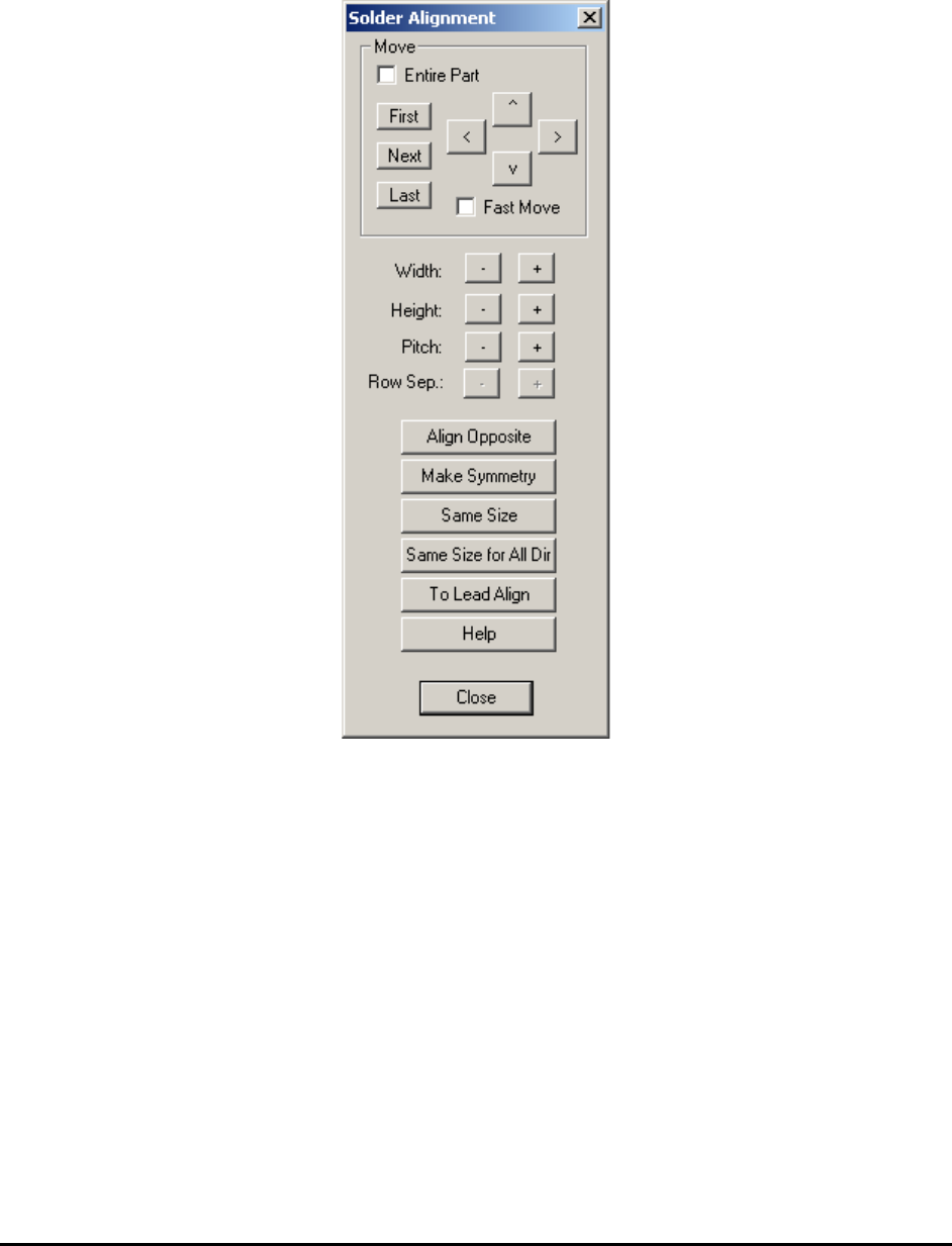
10.4.7 Solder Alignment
Using this dialog the user can move and size the solder inspection boxes.
Select Align.. from the Solder pop-up menu to open the Solder Alignment dialog.
The Width and Height buttons increase and decrease the rectangular area of the inspection box.
The Pitch buttons increase or decrease the pitch between inspection boxes.
The Row Sep. buttons are normally disabled. They are enabled only if the Row Count is greater
than 1. When they are enabled it adjusts the row separation for the pins.
The Align Opposite button aligns or creates the lead inspection in the opposite direction of the
part.
The Make Symmetry button moves the lead box so that it is symmetrical with respect to the
centroid of the part.
The Same Size button makes all the solder boxes with the same direction the same size.
The Same Size for All Dir button makes all the solder boxes, belonging to the same package,
the same size.
General Inspection Methodology 10-33
The To Lead Align button changes the focus from the Solder Alignment dialog box to the Lead
Alignment box.
The Help button launches internal help for this dialog.
10.5 X-Ray Inspection for BGA Device
YesAX software organizes inspections into three types: Marking, Lead Bank and Solder. Each
part can have any number and combination of these three types of inspections. When applying
X-Ray inspection methodologies for BGA devices, normally there is no marking inspection. The
available inspections are: lead bank and solder inspections. A BGA352 may have six lead banks
and 352 solder inspections.
There is only one light and one view for X-Ray inspection: Side light and X-Ray View. There
are several FOV (field of view) choices for X-Ray inspection: 1”, 0.5” and 0.25” FOV.
NOTE
0.25” FOV is not available for X3 AXI system inspections.
For each FOV there are several X-Ray power levels. Each power level has its own X-Ray tube
voltage, current and spot size settings.
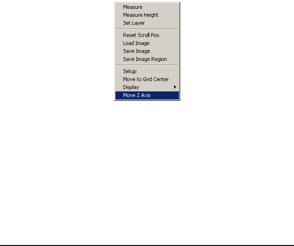
To change the FOV, press the right mouse button while pointing inside the Video area.
Select Move Z Axis to launch the Move Z dialog.