YesAX V3.1.2 - Software User Manual - 第131页
General Inspecti on Methodolo gy 10 - 37 It is somewhat tricky if you want to change the FOV of an X-ray inspection (e.g. from 1” FOV to 0.5” FOV). Here are the steps to do so: First use the Move Z dialog to move the Z s…
10-36 General Inspection Methodology
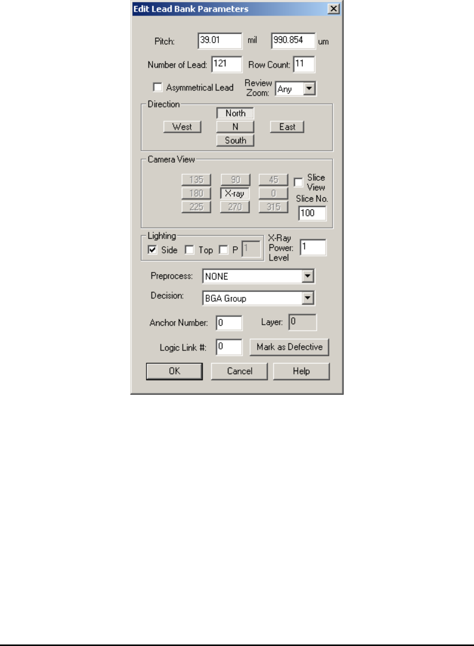
10.5.2.1 Edit Lead Bank Parameters
On this dialog the user sets the pitch of the BGA balls, the number of balls in the BGA lead bank,
the direction, the view, the lighting and the algorithm selection.
BGA lead banks will always have more than one Row Count, which is different from normal IC
components.
The Camera View for X-Ray images is always set to X-ray.
The Slice View should always be checked for 3D inspection and unchecked for 2D inspection.
The Slice No. must be specified for 3D inspection.
The Lighting for X-Ray images is always set to Side.
The X-Ray Power Level lists the power level number for the current lead bank.
The Preprocess for BGA lead bank is always set to NONE and the Decision is always set to
BGA Group.
General Inspection Methodology 10-37
It is somewhat tricky if you want to change the FOV of an X-ray inspection (e.g. from 1” FOV to
0.5” FOV). Here are the steps to do so: First use the Move Z dialog to move the Z stage to the
desire FOV, point the mouse to the Region of Interest (ROI), and open the Edit Lead Bank
Parameters dialog. Press the X-ray button (the button is already depressed) in the Camera View
group again, and then press OK to close the dialog. Double click near the video cross hair to
refresh the screen display; you will see the ROI box change from blue to green indicating the
FOV has changed.
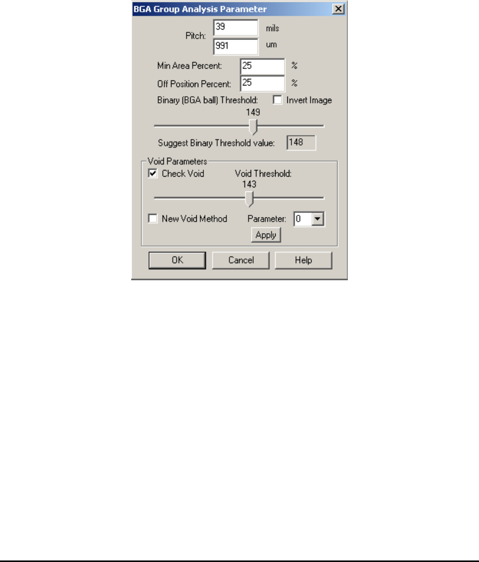
BGA Group Analysis Params launches the BGA Group Parameters dialog.
Pitch is the distance between each BGA balls, either in row or column. It can be in mils or
microns. (Typical values, 1500 um, 1270 um, 1000 um)
Min Area Percent sets up the threshold for detecting a BGA ball missing case. A BGA ball with
its area less than the minimum area will be caught as a missing ball. A value of 25% is typical
for this parameter. It can range from 5 to 40%.
Off Position Percent combined with pitch, defines the maximum distance (in the percentage of
pitch) that one BGA ball could be off from its original position. Set this parameter to detect off-
position solder balls. A value of 20% is typical for this parameter. It can range from 0 to 40%.
Binary (BGA ball) Threshold sets the binary threshold value which is used to convert gray
scale images into binary images. A good binary threshold value separates the majority of BGA
balls from their background and results in good measurement values. The Suggest Binary
Threshold Value is the pre-calculated value based on the current image. When the dialog is first
launched, the binary threshold value will be set equal to the suggested binary threshold value.
Later on you can select a different binary threshold value by moving the slider bar.
10-38 General Inspection Methodology
Invert Image checkbox if checked will invert the pixel value of the image before performing the
analysis.
Check Void checkbox if checked will calculate a void percentage for each BGA ball.
Void Threshold sets the binary threshold value which is used to convert gray scale images into
binary images and perform void calculations. Moving the slider bar will change the threshold
value and display a binary image instead of the original gray scale image.
New Void Method checkbox if checked will apply the new void detection algorithm instead of
the old one. Please make sure to select void threshold number less than the ball threshold number.
Moving the slider bar of void threshold will display a binary image. In this binary image only
pixels with gray scale between void threshold and ball threshold will be displayed. To fine tune
the shape of the void, user can select a number different than 0 in Parameter drop down box.
The available choices are 1 and 2. Bigger number will get rid of small unwanted voids but in the
mean time, change the shape of voids slightly. If the parameter number is set to a number
different than 0, the user can click the Apply button and see the actual void been detected on the
screen.
In addition to BGA Group, another algorithm for BGA inspection would be Image Subtraction.
This algorithm does not calculate numerical parameters of the BGA but instead uses a simple
image comparison principle. A reference image taken from a good part is subtracted from the test
image. The difference is the threshold to determine a pass or fail status.
Different Image = | Test Image – Reference Image |
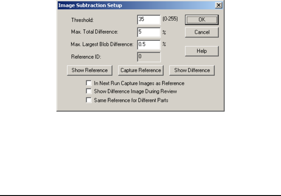
Image Subtraction Params.. launches the Image Subtraction Setup dialog for setting image
subtraction parameters.
The Threshold is the gray level difference between the corresponding pixels of the two images.
Pixels gray level difference below the threshold will be considered the same.
The Max. Total Difference is the maximum number of pixels that is different from the reference
image to be considered PASS, expressed in percentage. The Max. Largest Blob Difference is
the maximum numbers of pixels in the largest blob of the different image to be considered PASS.