YesAX V3.1.2 - Software User Manual - 第137页
General Inspecti on Methodolo gy 10 -4 3 Please be noticed that when user utilizes Pin Cad Import to crea te solder inspection box, the BGA Row and Column Info will be set to the specific value and the Direction will be …
10-42 General Inspection Methodology
If user utilizes the Pin Cad Import process (which is covered in early section) to import each
individual pin of BGA device into recipe, it is better to use the BGA Pin Inspection algorithm for
BGA solder inspection. The BGA Pin Inspection is like a combination of BGA group inspection
and BGA solder inspection. The difference is that BGA Pin Inspection runs on single solder joint
only while BGA group inspection is for lead inspection and runs on multiple solder joints. Once
BGA Pin inspection is applied to all solder inspection boxes, there is no need to create lead box
for current BGA device. The BGA Pin Inspection checks for bridges between BGA balls,
missing balls, insufficient solder and void defects.
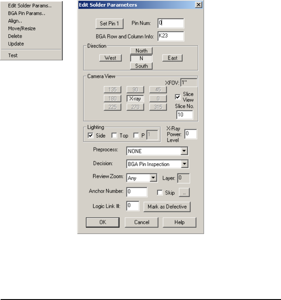
After the solder inspection box is created, open the Solder pop-up menu by pressing the right
mouse button while pointing inside the solder inspection box.
Edit Solder Params. – Launch the Solder Parameters dialog
Enter the current solders pin number in the Pin Num field.
The rest of the buttons on the dialog set the Direction, Camera View, Slice View, Slice No.,
Lighting and X-Ray Power Level for the inspection. For X-Ray inspection the Camera View is
always set as X-ray, the Lighting is always set to Side and the X-Ray Power Level needs to be
specified in the corresponding field.
General Inspection Methodology 10-43
Please be noticed that when user utilizes Pin Cad Import to create solder inspection box, the
BGA Row and Column Info will be set to the specific value and the Direction will be set to N
automatically. This is the differences between Pin Cad Import and normal Cad Import.
There is no specific preprocessing algorithm for BGA Pin Inspection.
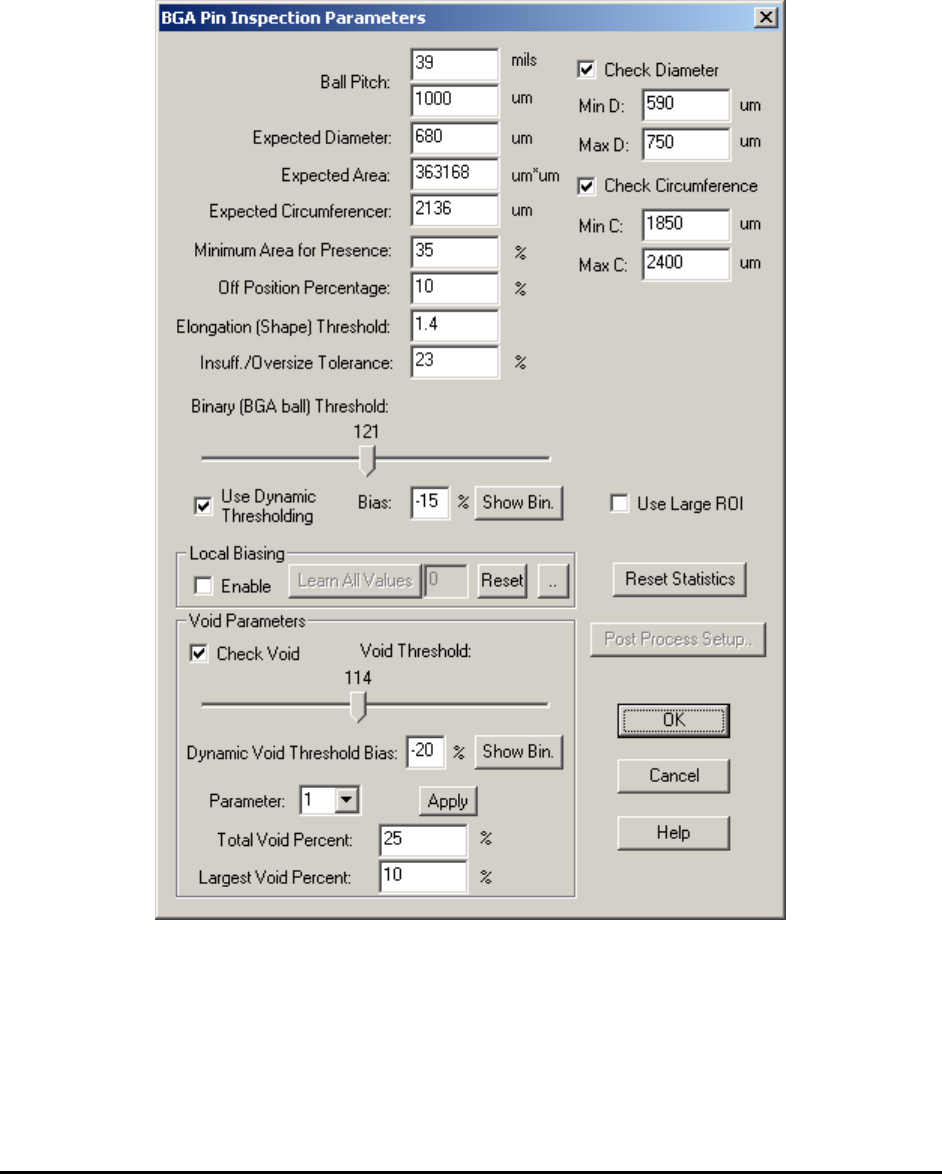
BGA Pin Inspection Setup – Launch the BGA Pin Inspection Parameters dialog.
Parameters inside this setup dialog box are similar to those from several other dialog boxes: the
BGA Group Analysis Parameters dialog box, the BGA Ball Analysis Parameters dialog box and
the Lead Blob Analysis Parameters dialog box. If user already familiar with the rest of inspection
algorithms, understanding this dialog box should be fairly easy.

10-44 General Inspection Methodology
Ball Pitch and Expected Diameter specify the pitch and ball diameter for current ball. Likely all
BGA balls belong to either same 2D package or same slice in 3D view will have the same pitch
number and ball diameter. The number of ball pitch also specifies the size of search window. The
size of search window is exactly the same as the pitch, not the size of the solder inspection box
as shown in screen.
Minimum Area for Presence specifies the minimum area percent parameter for detecting
missing defect. Off Position Percentage specifies the position off percent parameter for
detecting off position defect.
Binary (BGA ball) Threshold sets the binary threshold value which is used to convert gray
scale images into binary images. A good binary threshold value separates the majority of BGA
balls from their background and results in good measurement values.
Use Dynamic Thresholding checkbox if checked will apply dynamic threshold instead of binary
threshold which is specified by user for current inspection. The dynamic threshold method is
similar to the one in lead blob analysis algorithm. Bias (threshold bias) can be used to increase or
decrease the inspection sensitivity. Reducing the Bias e.g. – 10% will increase the sensitivity of
the detection. The Show Bin button displays the binary image.
Insufficient/Oversize Tolerance specifies the abnormal area percent parameter for detecting
insufficient and oversize defect.
Check Diameter checkbox if checked will apply Min D. and Max D. diameter threshold values
to the inspection results. A BGA ball with a diameter less than Min D. or greater than Max D.
will fail for size defect.
Check Circumference checkbox if checked will apply Min C. and Max C. circumference
threshold values to the inspection results. A BGA ball with a circumference less than Min C. or
greater than Max C. will fail for size defect.
Use Large ROI checkbox if checked will apply a larger ROI to current inspect box. This will
particularly help catching the bridge defect.
Check Void checkbox if checked will calculate void related measurements for current BGA ball.
Void Threshold sets the binary threshold value which is used to convert gray scale images into
binary images and perform void calculations. Moving the slider bar will change the threshold
value and display a binary image instead of the original gray scale image. Please make sure to
select void threshold number less than the ball threshold number. Moving the slider bar of void
threshold will display a binary image. In this binary image only pixels with gray scale between
void threshold and ball threshold will be displayed. To fine tune the shape of the void, user can
select a number different than 0 in Parameter drop down box. The available choices are 1 and 2.
Bigger number will get rid of small unwanted voids but in the mean time, change the shape of
voids slightly. If the parameter number is set to a number different than 0, the user can click the
Apply button and see the actual void been detected on the screen.
The Total Void Percent and Largest Void Percent threshold needs to be set by the user to pick
up void defects. These two parameters are similar to those in BGA Ball Analysis algorithms. The
default values for these two parameters are 25 and 10, respectfully.