YesAX V3.1.2 - Software User Manual - 第141页
General Inspecti on Methodolo gy 10 - 47 6. Enter the correct parameters for the lead bank; this includes the pitch, the total number of leads, and the row count. 7. From the Lead bank pop-up menu, select Train Solders .…
10-46 General Inspection Methodology
9. Run the inspection.
10. If necessary, repeat step B one more time. The learn local bias process will perform
one more time based on the current local bias number. Please be noticed that the
lower limit and upper limit for local bias is -50 and 50, respectively.
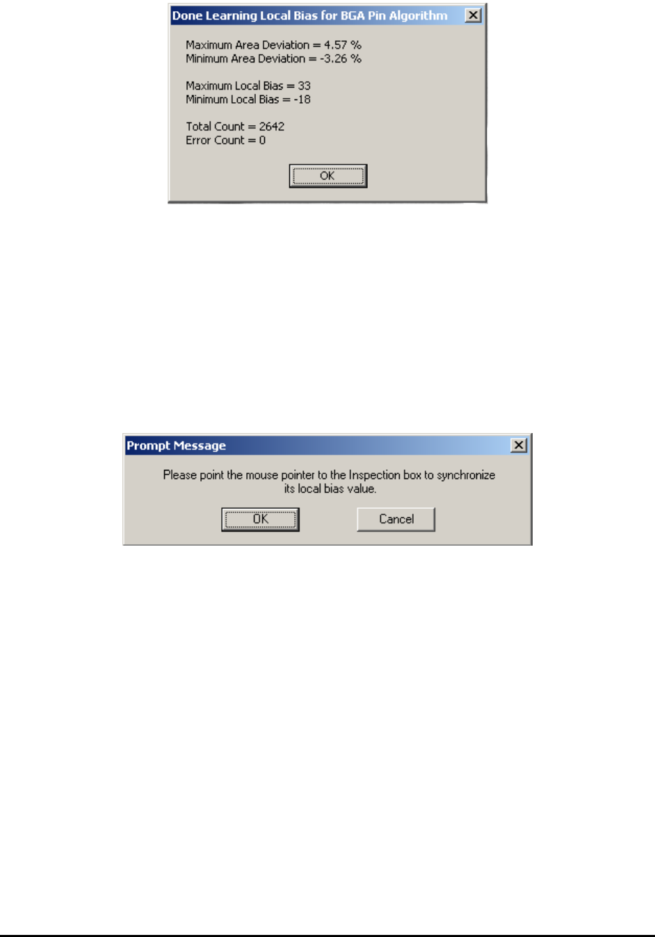
11. If possible, the user can manually type in the local biasing number for each
individual ball. To apply the same local biasing number to other balls, the user
needs to click the .. button first to dismiss the dialog. The following dialog will
show up. Then the user can follow the instruction and click any BGA ball which he
likes to put the same local biasing number on and click OK to dismiss this message
box and apply the changes.
10.5.4 Steps to Create a New BGA Package
There are times when you may need to create a new BGA package from scratch. Creating new
packages for different BGA devices is not difficult. Below is the general procedure:
1. Create the part body in vision or X-ray view; enter the Reference ID, part number and
package.
2. Turn on the X-ray and switch to X-ray view, experiment with different FOVs and Power
levels to find out the desirable FOV and power level. Make the selection in your mind;
you will need to enter them later.
3. Move to a large field of view and try to have the entire BGA in one view. Count the
number of balls by row and column. Measure the pitch of balls by the measurement
function. As for the pitch of BGA, most BGA devices will have one of the following
numbers: 0.5mm, 0.75mm, 0.8mm, 1.0mm, 1.27mm and 1.5mm.
4. You will need all the information later.
5. For full array BGA train a lead bank that includes all the balls. For perimeter array BGA
train a lead bank that includes all the balls for one direction.

General Inspection Methodology 10-47
6. Enter the correct parameters for the lead bank; this includes the pitch, the total number of
leads, and the row count.
7. From the Lead bank pop-up menu, select Train Solders.
8. From the Solder pop-up menu, select Align, and line up the solder inspection boxes.
9. Hide the solder inspection boxes by pressing the button on the tool bar.
10. From the Lead bank menu, select Break into Sectors, to break the lead inspection box
into sectors that will fit into the FOV selected in step #2. The FOVs are rectangular; you
want to break the Lead bank into small enough sectors that will fit in the smaller
dimension (Y dimension) of the desired FOV. This way the package will work even if it
needs to be rotated 90 degree.
11. Move the Z axis into the selected FOV. Switch the FOV of the Lead bank to the selected
FOV. Setup other lead parameters.
12. Setup BGA Group parameters, then update the parameters into other lead sectors.
13. Un-hide the Solder inspection box by pressing the again. Display the solder pop-up
menu and setup the solder inspection parameters.
14. Setup the BGA ball parameters then update the parameters to other solder inspection
boxes.
15. For perimeter array the user needs to repeat step 3 to 13 for lead banks in the other
directions.
For X3 AXI system inspection programs, it is necessary to create a 3D BGA package based on
the existing 2D package. Below is the procedure:
1. Create normal BGA package in 2D. Try to align solder box and make sure all solder
boxes cover the whole ball. If BGA group is used for lead inspection and that lead bank is
bigger than the current FOV, the large lead bank may needs to be broken into smaller
ones. When breaking the lead bank, the general rule is to assign less 3D sites to cover the
whole package.
2. Select 3D sites and create 3D slices for BGA. During this period it is possible to re-
adjust the power level or even FOV. It is important to set the right FOV at the beginning
of programming. Adjusting the power level for a package is easy while adjusting all
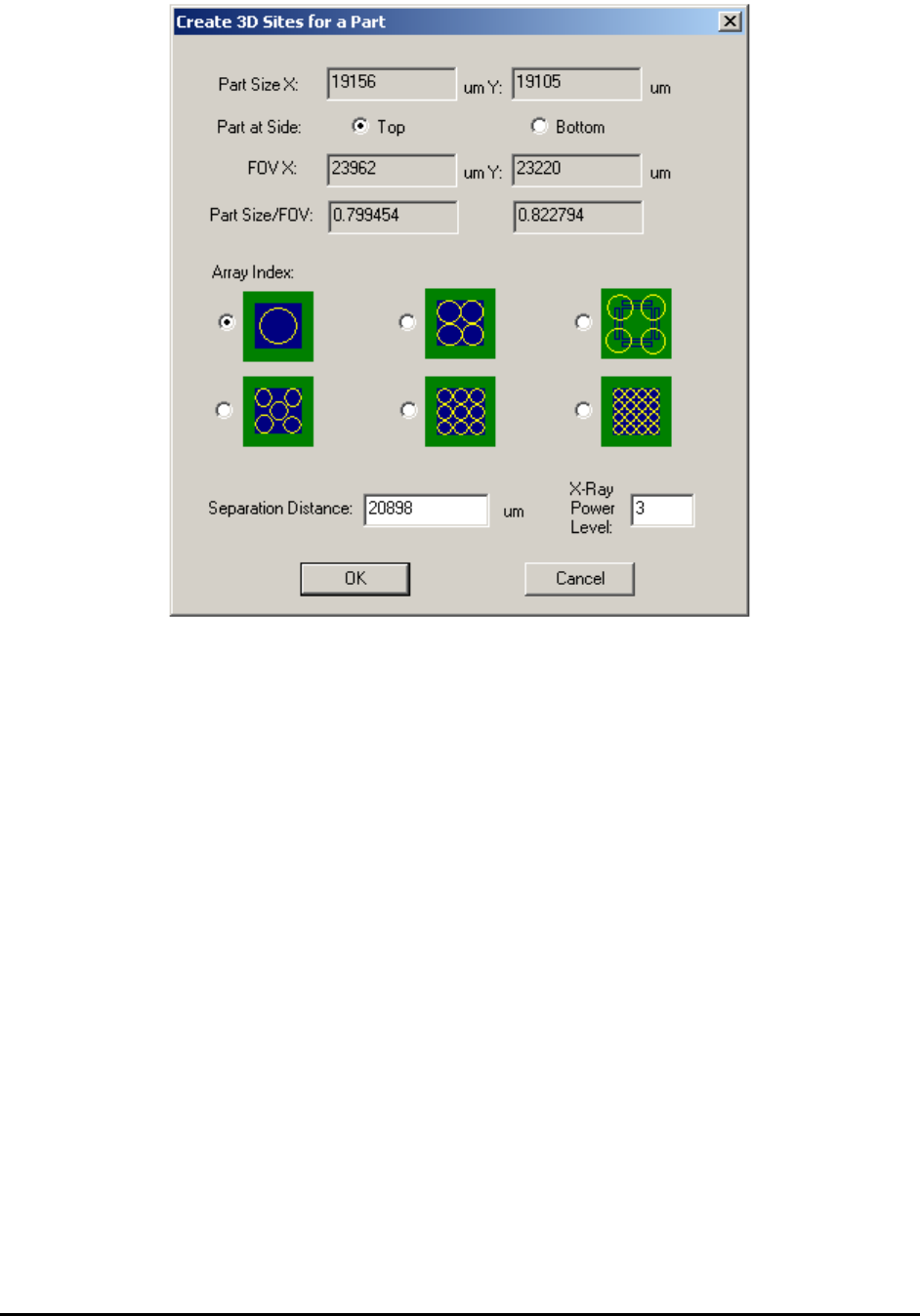
inspection boxes to a different FOV may be complicated. The user can either locate 3D
sites manually or use some automatic way. Inside part body when user right mouse clicks
any open space and launch the part menu, execute Create 3D Sites… command will
launch the following dialog.
10-48 General Inspection Methodology
There are six different layouts to choose from. Each layout provides a solution of
different number and location of 3D sites. User may select either one of them. There is
one default separation parameter for each layout, which indicate how much off those 3D
sites are from the center of the package. User can either use the default parameters or
type in a different number. Once OK button’s been presses, the corresponding future 3D
sites will be added to the recipe and to the map view window automatically.
3. Unless the board being inspected is very flat, always allocate laser reference sites for
these 3D sites and run height profile. After height profile’s been created, the height map
of all 3D sites will become available for inspection.
4. For BGA mounted on top side of the board, set middle layer to slice number 0 first and
then adjust surface offset, make sure to get the largest ball size as possible. During initial
training it is preferable to use a good BGA sample (the largest ball diameter appears the
middle layer of the ball).
5. Measure the ball diameter and get ready to add the BGA package slice and pad slice to
the 3D site and the BGA package. Since BGA balls normally collapse after reflow. It is
preferable to pick the slice which is about 70% to 80% of ball diameter away from the
middle slice. For example, if the maximum ball diameter is 36pixel under 1” FOV, we
may want to use slice number -15 and 15 for package slice and pad slice, respectively.
6. Set slice number to 0 and then use the “IB to current slice” function and convert all
inspection boxes from 2D view to 3D slice view with slice number 0. It is a good idea to
have the name of the package and part ready so we can update the package and part
library.