YesAX V3.1.2 - Software User Manual - 第146页
11 -2 3D X-Ray Inspection Methodology 2D X-ray image showing Top and Bottom Interference Top and Bottom solder joint separated by 3D X-ray imaging 11.1.2 Detect “Head in Pill ow ” Joint Condi tions on B G A Head- in -pil…

3D X-Ray Inspection Methodology 11-1
11 - 3D X-Ray Inspection Methodology
The X3 AXI system is an automated inline X-Ray inspection system with full 3D capabilities.
The X3 AXI system can not only do a full 2D inspection of a PCB but it can also do a 3D
inspection of the PCB. The X3 can also combine 2D and 3D to optimize between speed and
capability by using 3D only where needed.
A standard 2D X-Ray machine only has one X-Ray view, the top-down view that sees through
an object from top to bottom. For the X3, other than the regular top-down view, it can “look” at
the object from 8 different side angles and then by combining them using Digital Tomosynthesis
Reconstruction algorithms, creates slices parallel to the board surface. These slices can separate
the top side from the bottom side so that each side of the double sided board can be
independently analyzed.
The height offset of the top surface of the board can be measured using a laser device and this
information is used to compensate for board warp. It is possible to setup the parameters and the
position where the laser measurements will have to be made and the range over which the
measurement will be effective.
Although the X3 AXI system is a fully automated 3D x-ray inspection system, it has significant
manual capabilities. You can simply load a board, position the part under x-rays, select the
appropriate power level, add/edit a 3D site and scroll up and down perpendicular to the surface
of the board.
11.1 Key Applications for 3D Inspection
11.1.1 Separate Top and Bottom Side Parts
Because X-ray is able to passing through the circuit board, it produces a density projection of the
field of view. The dense areas such as the solder joints appear as a dark area on the image. For
double sided boards with solder joints on both sides of the board, the dark areas from two sides
could overlap. That causes difficulty for inspecting the quality of the solder joints when they are
obscured by the solder joints from the other side. 3D X-ray imaging solves that problem by
creating slices represent different side. Solder joint from the top side would apparent in a
different slice as the solder joints from the bottom side. The separation allows inspection for
solder quality on both side of the circuit board.
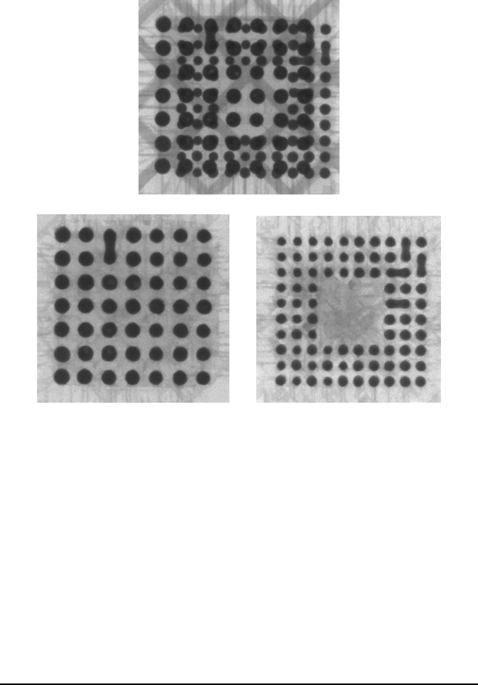
11-2 3D X-Ray Inspection Methodology
2D X-ray image showing Top and Bottom Interference
Top and Bottom solder joint separated by 3D X-ray imaging
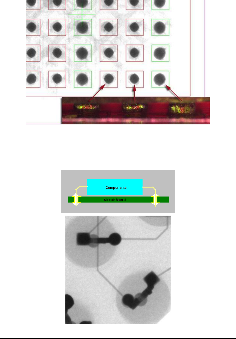
11.1.2 Detect “Head in Pillow” Joint Conditions on BGA
Head-in-pillow defect is the incomplete coalescence of the solder joint between a BGA (Ball-
Grid Array) and the printed solder paste. For some reason, the printed solder and the package’s
solder spheres do not come together to form a single mass. In some instances there seems to be
an oxide film on the surface of the molten solders. In other instances, it appears that upon
cooling, the exterior has already cooled enough to prevent the coalescence of the printed paste
and the sphere. It is a difficult defect to detect using conventional 2D X-ray systems, because
from the top the good joints and the bad joints look very similar. Some 2D X-ray system vendors
claim that such condition can be detected with minute variation in ball diameters. The true telling
feature is in the change in ball diameter we move up and down the ball. Such changes are best to
be detected using 3D slicing capabilities. The maximum ball diameter for Head-in-Pillow joints
tend to be at a higher Z than the normal joints. Slice at the board level tend to reveal a smaller
ball diameter as show in the picture below.
3D X-Ray Inspection Methodology 11-3
11.1.3 Detect Barrel Fill Condition for PTH
For plated through hole (PTH) circuit boards, component leads (pins) go from the component
side pass through the board and be soldered on the solder side of the board. For high reliability
circuit the solder should be wetted into the hole and completely fill the barrel. 3D X-ray imaging
can be used to verify the solder condition inside the barrel of the PTH circuit board.