YesAX V3.1.2 - Software User Manual - 第157页
3D X-Ray Inspection Methodolo gy 11 - 13 2. When placing laser references on board, it is preferable to put them at the same kind of surface or layer. It is also better to keep these laser references away from silkscreen…

11-12 3D X-Ray Inspection Methodology
Display Statistics if pressed will launch another dialog and show statistics of measurement of
current surface reference point. If the standard deviation and worst deviation are both very small
for current point, the calculation is stable and the reference point is well defined. Otherwise, it is
preferable for user to check the location of current reference points and other parameter settings
and make sure everything is ok.
The math: To help user better understand the calculation of height reference, below is the
formula:
Height Measurement Output = Initial Measurement + Local Offset – Board Offset – Board
Offset Bias
Here the Initial Measurement number was calculated from surface reference algorithm directly.
The Local Offset was set by user and can be used to compensate for height difference between
different surfaces. The Board Offset was the average height of height anchors (without minus
Board Offset and Board Offset Bias) and was calculated automatically every time inspection
runs or user performs a Profile Board Height command. The Board Offset Bias was set by user
during recipe programming.
Any laser surface reference with height anchor option turned on will be served as height
reference only and should not contribute to any z map compensation test. This is to offset the
board height differences between different boards and make sure the height information of the
same 3D site will be consistent among different boards.
Laser reference placement:
Laser references are important for 3D program. For board with an uneven surface or has severe
warp issue, using laser references and putting them in the right location will help software find
the surface map in that particular 3D site and generate the right slice which is parallel to real
board surface. When putting laser references on the board, there are several rules that user needs
to follow.
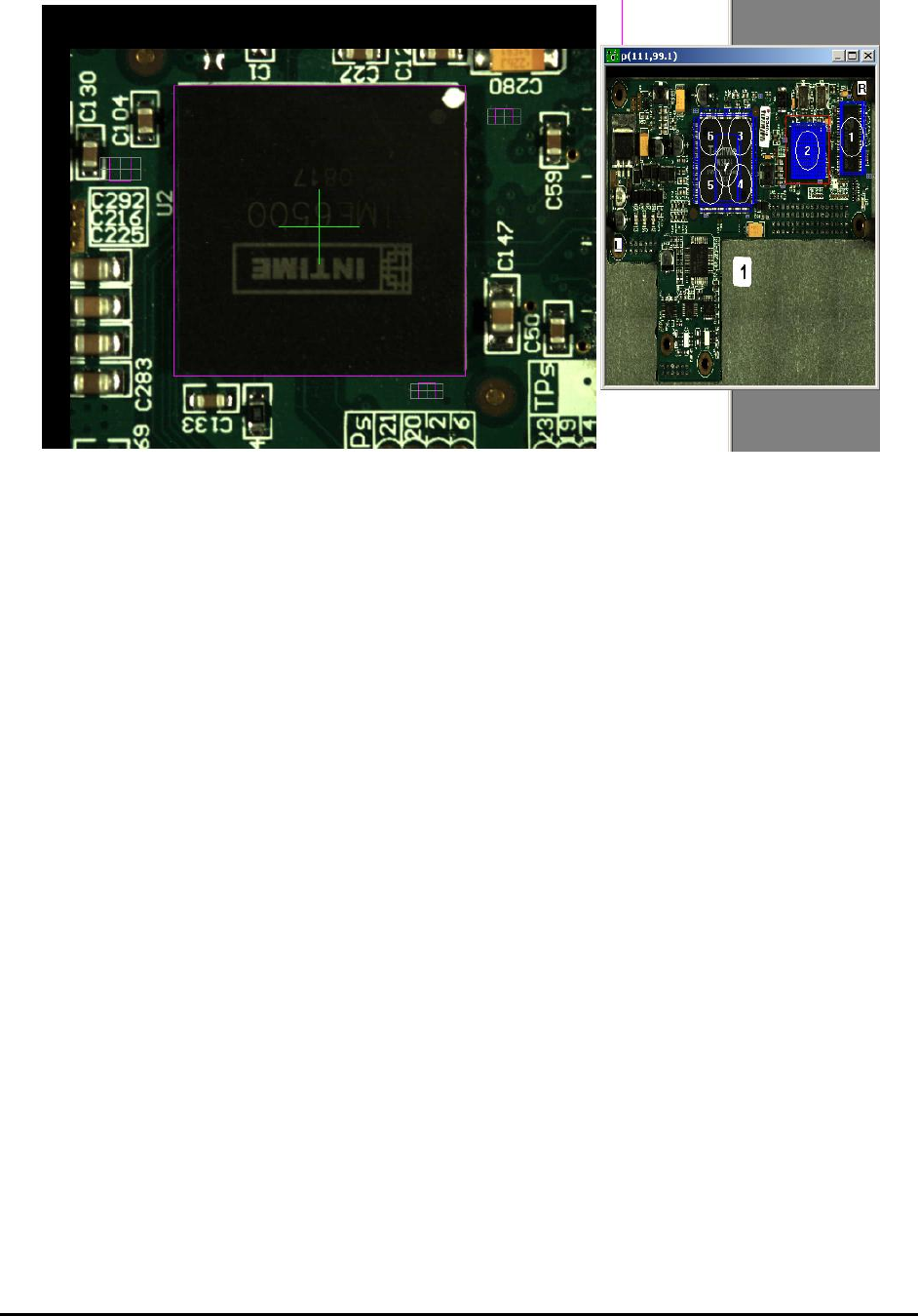
1. For each 3D site, if possible, the user should allocate 3 laser pointers as height references.
They need to be away from each other and not far away from the center of 3D site. As
shown in picture below, the current 3D site, which includes a BGA device, uses three
laser reference points well separated away from each other to construct the height map. In
this case the position of these laser references should be as close to the device as possible.
3D X-Ray Inspection Methodology 11-13
2. When placing laser references on board, it is preferable to put them at the same kind of
surface or layer. It is also better to keep these laser references away from silkscreen,
component names in big white labels and any shinning object, like solder joints and metal
caps. Other than some special devices like PoP (package on package), the laser reference
should be put on the surface of the PCB if possible.
3. If it’s very difficult for user to allocate laser references on top of board surface, it is OK
to put laser references on top of the component or a different surface. Please make sure to
use laser references on same surface for the 3D site and set up the local offset numbers
for those laser references carefully. For laser references reside on same kind of surface,
their local offset should set to same number.
4. If the board is relatively flat (e.g., a fixture is being used to load and unload the board), it
is possible for user to allocate only one laser reference for the 3D site. In this case the
height of this laser reference will be used as the height offset of that 3D site directly.
5. It is OK for user to use 2 laser references for a 3D site, if it is really difficult to find a
good location for the 3
rd
laser pointer.
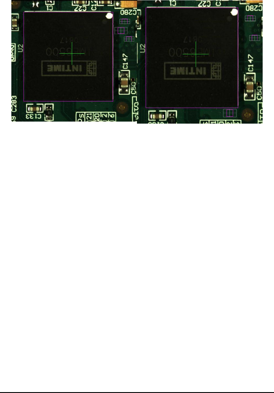
6. It is not a good idea to use 3 laser references, which is either very close to each other
(lower left image), or almost on the same line (lower right image) for the 3D site. In
either case the height map generated by these three laser references may not reveal the
real tilted situation of the board surface. If user has difficulty locating a third laser
reference, he can either use the force reference 0 option or just use 2 laser references for
current 3D site.
11-14 3D X-Ray Inspection Methodology
During 3D programming it is important to allocate at least three height reference points per 3D
site and make sure each 3D site has the best height reference locations available. YesAX
software has provided user an easy way to tell what height references were used by the current
3D. First, user needs to make sure to run Profile Board Height command once or run the
inspection once to create/refresh the height map. After that if user saves the recipe the latest
reference height information will be saved to ZMap.txt file which is under current recipe folder.
If user only runs Profile Board Height command once, the next thing he needs to do is to switch
to 3D mode, go to first 3D site and then use the >> navigation button inside the 3D control
window and go through the rest of the 3D sites. If user doesn’t want to go through every 3D site,
it is possible for him to only go through those 3D sites which he’s interested. After that all he
needs to do is to maximize the map view window. The window will show extra information
other than the normal blue boxes. Below is a screenshot of part of the window: