YesAX V3.1.2 - Software User Manual - 第167页
Other X-Ray Inspection Features 12 -1 12 - Other X-Ray Inspection Features The X2/X3 AXI system is a fully automated inline X-Ray inspection system. However, there are several features in YesAX software that allow you do…
11-22 3D X-Ray Inspection Methodology
Align Source to II is the first step of X-ray calibration. The procedure of this step is similar to
that of X2. But the actual hardware adjustments are quite different. Hardware adjustments for the
X3 AXI system are always more complicated and more difficult. The hardware adjustments are
normally done in factory before the unit is shipped.
X-ray Vision Offset, X-ray FOV, X-ray Power Level, X-ray Cam Angle and X-ray Cam
Focus these tests are quite similar for both X2 and X3.
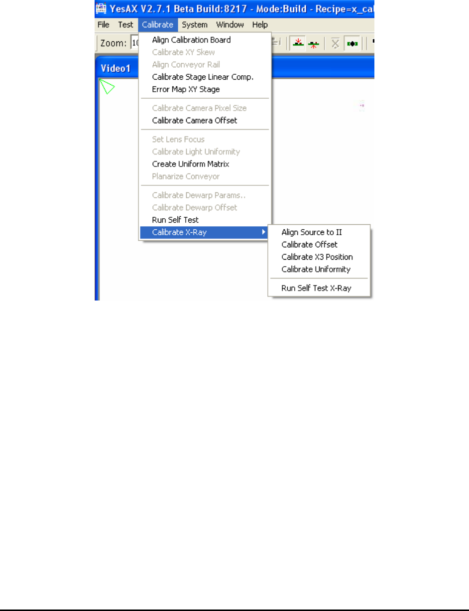
X Power Uniformity for X3 is quite different from the X Power Uniformity test for X2. For X3
this item has been grayed out in self-test dialog. To do the test, the user needs to load a special
test board (same size as X-ray calibration board, and share the same recipe file: x_cal_board.rcp)
and do the X Power Uniformity test from menu, as seen from picture in left.
X3 Position is a unique test for X3 AXI system. This one calibrates top stage positions for all 3D
side angle views. On prompt user can select to either do 8 position calibration only or do a full
calibration for all positions.
Detector Perpendicularity is also a unique test for X3 AXI system. This one tests the
perpendicularity of top detector (X-ray camera) plane and see whether the top plane is parallel to
the XY moving stage. The software test is very simple. But the actual hardware adjustments are
more complicated. Normally the hardware adjustments are done in factory before X3 is shipped
to customer site.
The Confirm Each Target’s Location Visually checkbox if checked paused after each X-ray
target’s location during the calibration process and give the user an opportunity to visually verify
the correct location of each target. The feature is especially useful when NORDSON
YESTECH’s tech-support engineers need to calibration a machine remotely via WebEx.
Other X-Ray Inspection Features 12-1
12 - Other X-Ray Inspection Features
The X2/X3 AXI system is a fully automated inline X-Ray inspection system. However, there are
several features in YesAX software that allow you do some manual X-Ray inspection, like the
YTX-X1 manual X-Ray inspection system. These features add more flexibility to the system and
provide more power to fully utilize X-Ray inspection capabilities. This section details these
features.
NOTE
These features are designed specifically for X-Ray images and not for images
acquired by top camera.
12.1 Image Filters and Restore Command
Inside the X-Ray view window, position the current cursor outside any inspection box (part box,
lead box, solder box, etc…). Right mouse click to launch the Video pop-up, then select the
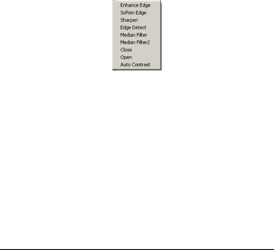
Filters sub-menu.
Most manual inspection functions can be found within this menu.
The Filters sub-menu consists of functions that perform two dimensional filters upon the current
image and display the results. These filters are designed to emphasize or de-emphasize specific
features in the image. If a filter or multiple filters are applied to a captured image, the original
image can be recovered by selecting the Restore function in the pop-up menu.
NOTE
These filters only apply to X-Ray images. All available filter options will be
grayed out when this menu is shown under top view.
12.1.1 Enhance Edge
The Enhance Edge function emphasizes the edge content of the image. Local regions of similar
gray level, or slowly varying gray level are suppressed and areas of dissimilar gray level that
change significantly are accentuated. The edge enhancement filter operator is a high-pass filter; it
retains the high frequency content of the image and rejects the low frequency content.

12-2 Other X-Ray Inspection Features
12.1.2 Soften Edge
The Smooth Edge function is the opposite of the Enhance Edge filter. It de-emphasizes the edge
content of the image. Local regions of similar gray level, or slowly varying gray levels are
accentuated and areas of dissimilar gray level that change significantly are suppressed. The edge
enhancement filter operator is a low-pass filter; it retains the low frequency content of the filter
and rejects the high frequency content.
12.1.3 Sharpen Image
The Sharpen Image function is a combination of the two previous filters: an Edge Enhancement
filter followed by an Edge Smoothing filter.
12.1.4 Edge Detect
The Edge Detect function applies an Edge Detect filter to the image and plots the edge map.
Compared to the Enhance Edge function, the Edge Detect function provides you with more
information about all the edges in the whole image.
12.1.5 Median Filter
The Median Filter function applies a median filter to the image. With this filter, each pixel is
determined by the median value of all pixels in a selected neighborhood (in this median filter
case, it’s a 3 pixel by 3 pixel operator with the selected pixel in center). Median filter is very
good at removing strong spikes, like isolated noise, from image. Also compared to the Soften
Edge function, Median Filter tends to preserve the edge and keep the small details of the image.
12.1.6 Median Filter2
The Median Filter2 function applies a median filter to the image. Different from Median Filter,
the Median Filter2 uses a 5 pixel by 5 pixel operator instead of a 3 by 3 operator. Thus the
Median Filter2 will tend to get rid of more noises but also lose more details, compare to the
Median Filter.
The Restore function recovers the original, captured X-Ray image in the current image window.
Even if multiple filters have been applied to the image, the Restore function can go back to the
original or captured image and remove any effects applied by these filters. If you open the
original image and then do live and capture, or you perform live and capture several times, only
the last image captured will be restored. The Restore function won’t be available for a newly
captured or loaded image without applying any filters.
12.2 3D Rendering
The 3D Rendering function provides the user with a tool to visualize image data variation in a
3D space. Given a region of interest (ROI) in an image, the function generates and displays a 3D
surface where changes of surface height reflect changes of pixel values in the image ROI. The
figure below is an image ROI and its 3D rendering shown side by side. The function also allows
the user to control the way the surface is rendered and interactively manipulate the rendered
picture.