YesAX V3.1.2 - Software User Manual - 第169页
Other X-Ray Inspection Features 12 -3

12-2 Other X-Ray Inspection Features
12.1.2 Soften Edge
The Smooth Edge function is the opposite of the Enhance Edge filter. It de-emphasizes the edge
content of the image. Local regions of similar gray level, or slowly varying gray levels are
accentuated and areas of dissimilar gray level that change significantly are suppressed. The edge
enhancement filter operator is a low-pass filter; it retains the low frequency content of the filter
and rejects the high frequency content.
12.1.3 Sharpen Image
The Sharpen Image function is a combination of the two previous filters: an Edge Enhancement
filter followed by an Edge Smoothing filter.
12.1.4 Edge Detect
The Edge Detect function applies an Edge Detect filter to the image and plots the edge map.
Compared to the Enhance Edge function, the Edge Detect function provides you with more
information about all the edges in the whole image.
12.1.5 Median Filter
The Median Filter function applies a median filter to the image. With this filter, each pixel is
determined by the median value of all pixels in a selected neighborhood (in this median filter
case, it’s a 3 pixel by 3 pixel operator with the selected pixel in center). Median filter is very
good at removing strong spikes, like isolated noise, from image. Also compared to the Soften
Edge function, Median Filter tends to preserve the edge and keep the small details of the image.
12.1.6 Median Filter2
The Median Filter2 function applies a median filter to the image. Different from Median Filter,
the Median Filter2 uses a 5 pixel by 5 pixel operator instead of a 3 by 3 operator. Thus the
Median Filter2 will tend to get rid of more noises but also lose more details, compare to the
Median Filter.
The Restore function recovers the original, captured X-Ray image in the current image window.
Even if multiple filters have been applied to the image, the Restore function can go back to the
original or captured image and remove any effects applied by these filters. If you open the
original image and then do live and capture, or you perform live and capture several times, only
the last image captured will be restored. The Restore function won’t be available for a newly
captured or loaded image without applying any filters.
12.2 3D Rendering
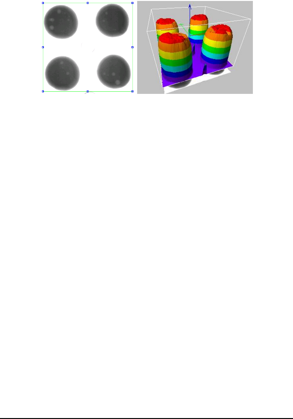
The 3D Rendering function provides the user with a tool to visualize image data variation in a
3D space. Given a region of interest (ROI) in an image, the function generates and displays a 3D
surface where changes of surface height reflect changes of pixel values in the image ROI. The
figure below is an image ROI and its 3D rendering shown side by side. The function also allows
the user to control the way the surface is rendered and interactively manipulate the rendered
picture.
Other X-Ray Inspection Features 12-3
12-4 Other X-Ray Inspection Features
12.2.1 Getting Started
To use the 3D Rendering function, select the 3D Rendering command from the Inspect menu on
the menu bar. The 3D Rendering dialog box is displayed on the right side of the screen, and also
a green rectangular box is displayed on the currently active image window.
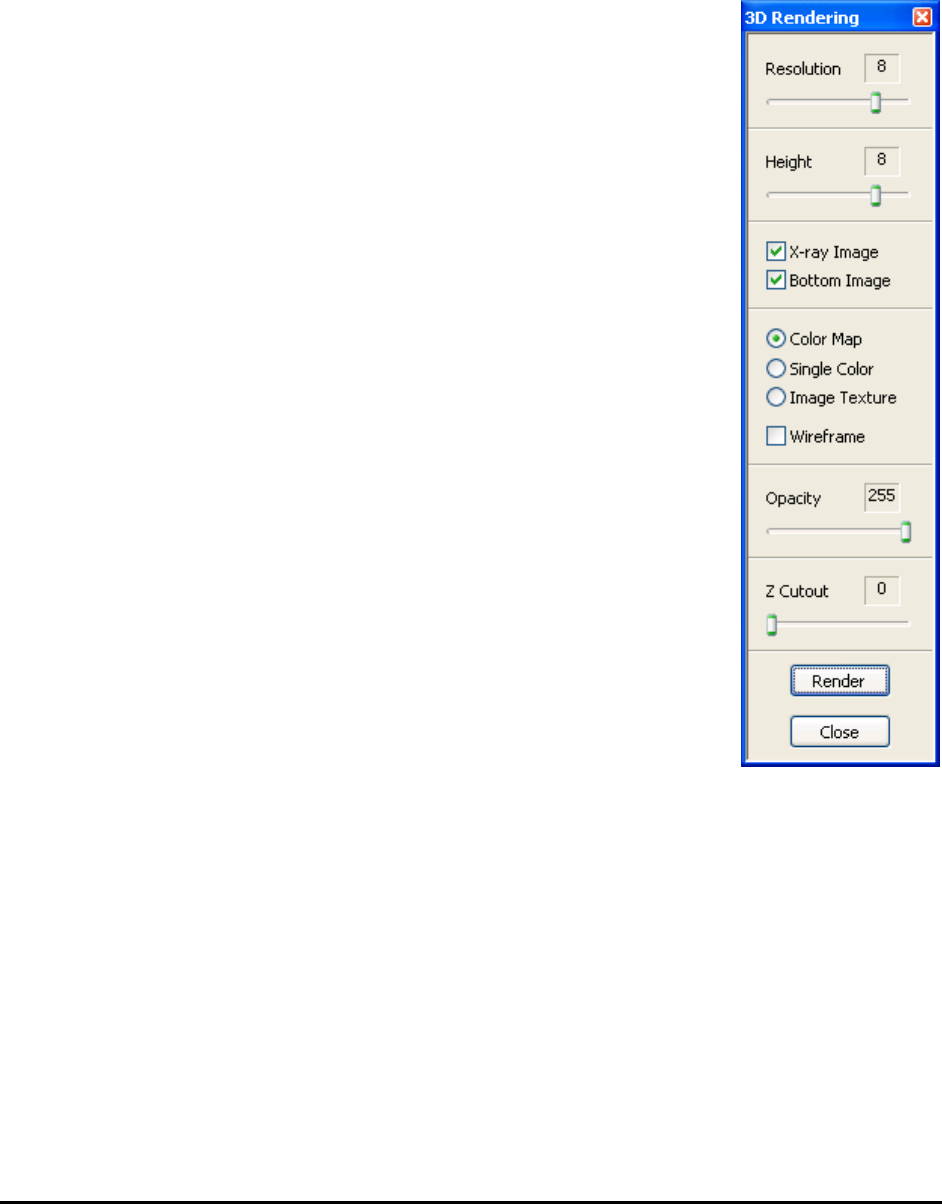
The 3D Rendering dialog box shows various settings that the user can
adjust to achieve various effects for the rendered surface. The figure to the
right shows all the default values for the settings in the dialog box.
Typically, the user adjusts the green box in the image to define an ROI,
then if needed, adjusts some settings in the dialog box, finally pressing the
Render button. The 3D Rendering window is displayed with a picture of
the rendered surface shown in the window.
The rendered surface is drawn within a box. At the center of the box are
three arrowed lines which respectively denote (red) X axis, (green) Y axis
and (blue) Z axis.
When the 3D Rendering window is open, changing setting in the 3D
Rendering dialog, will be instantly update the picture in the 3D Rendering
window to reflect the changed setting.
To render a different area in the image, adjust the green box in the image
to define a new ROI, and then press the Render button in the dialog box.
To save the 3D Rendering image to a file, click the right mouse button
while pointing anywhere inside the 3D Rendering window. A menu item
with the Save Image option opens. Specify the name and path of the
bitmap file in the file save dialog and click OK. A copy of the current 3D
Rendering image is saved to the specific location as an uncompressed
bitmap file.
NOTE
Bitmap format is the only available choice in this function.
When finished using the 3D Rendering function, press the Close button to close the 3D
Rendering dialog box, or close the 3D Rendering window that displays the rendered surface. If
you close the image window that contains the green box used by the 3D Rendering function, the
3D Rendering function will also shut down.