YesAX V3.1.2 - Software User Manual - 第170页
12 -4 Other X-Ray Inspection Features 12.2.1 Getting Started To use the 3D Rendering function, select the 3D Rendering c ommand from the Inspect menu on the menu bar. The 3D Rendering dialog box is displayed on the right…
Other X-Ray Inspection Features 12-3
12-4 Other X-Ray Inspection Features
12.2.1 Getting Started
To use the 3D Rendering function, select the 3D Rendering command from the Inspect menu on
the menu bar. The 3D Rendering dialog box is displayed on the right side of the screen, and also
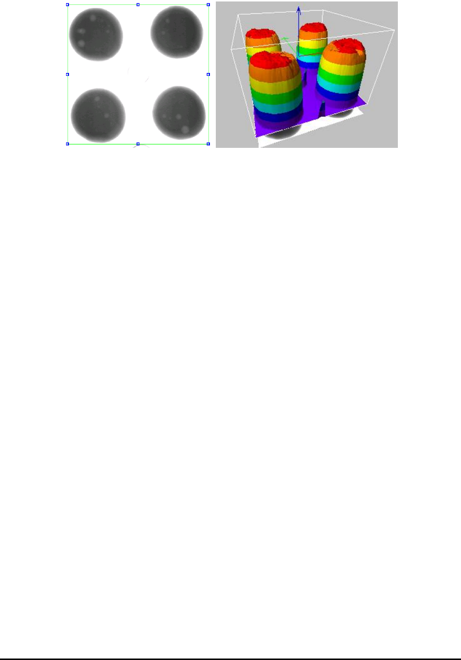
a green rectangular box is displayed on the currently active image window.
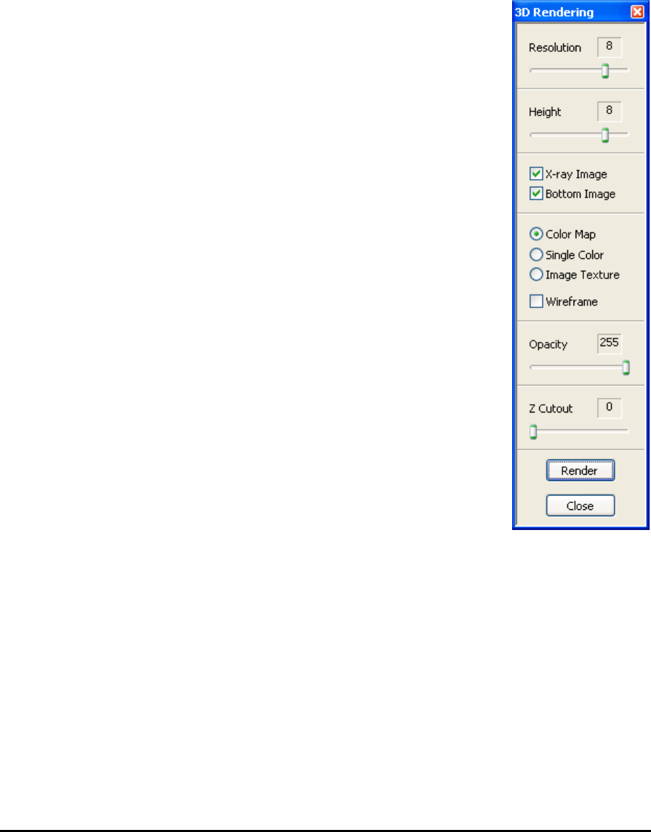
The 3D Rendering dialog box shows various settings that the user can
adjust to achieve various effects for the rendered surface. The figure to the
right shows all the default values for the settings in the dialog box.
Typically, the user adjusts the green box in the image to define an ROI,
then if needed, adjusts some settings in the dialog box, finally pressing the
Render button. The 3D Rendering window is displayed with a picture of
the rendered surface shown in the window.
The rendered surface is drawn within a box. At the center of the box are
three arrowed lines which respectively denote (red) X axis, (green) Y axis
and (blue) Z axis.
When the 3D Rendering window is open, changing setting in the 3D
Rendering dialog, will be instantly update the picture in the 3D Rendering
window to reflect the changed setting.
To render a different area in the image, adjust the green box in the image
to define a new ROI, and then press the Render button in the dialog box.
To save the 3D Rendering image to a file, click the right mouse button
while pointing anywhere inside the 3D Rendering window. A menu item
with the Save Image option opens. Specify the name and path of the
bitmap file in the file save dialog and click OK. A copy of the current 3D
Rendering image is saved to the specific location as an uncompressed
bitmap file.
NOTE
Bitmap format is the only available choice in this function.
When finished using the 3D Rendering function, press the Close button to close the 3D
Rendering dialog box, or close the 3D Rendering window that displays the rendered surface. If
you close the image window that contains the green box used by the 3D Rendering function, the
3D Rendering function will also shut down.

Other X-Ray Inspection Features 12-5
12.2.2 Using 3D Rendering Dialog
The 3D Rendering dialog contains the settings that control how the surface is rendered and
displayed. All the settings, as well as the positions and sizes of the image ROI and the 3D
Rendering window, will persist after the function or program exits.
Resolution: The Resolution value ranges from 1 to 10. It controls how many pixel samples from
the image ROI are used to render the 3D surface.
The higher the resolution, the more pixels are used. The more pixels used, the more accurately
the rendered surface reflects the original image data variation within the ROI and the more time
and memory space it takes to do the rendering.
Height: The Height value ranges from 1 to 10. It changes the height of the rendered surface. The
higher the value, the more stretched the surface appears along the Z axis.
X-ray Image: This is a flag that tells the function how to interpret the image data. When this flag
is checked, the image is assumed to be an X-ray image. For an X-ray image, we are more
interested in dark areas, so the darker areas in the image correspond to higher areas on the
rendered surface. Because this software mostly deals with X-ray images, this flag should usually
be left checked. If the flag were unchecked, the rendered surface would turn upside down,
because the bright areas would stand out.
Bottom Image: When this flag is checked, the original image area in the ROI is drawn under the
rendered surface. It makes it somewhat easier for the user to visualize the relation between the
image ROI and the rendered surface.
Color Map: When this option is selected, the rendered surface is drawn with pseudo-coloring.
Eight colors are used to paint the surface areas at different levels of height. There are 256 levels
of height (because there are 256 image gray levels). Each color represents 32 consecutive levels.
For instance, the areas that take the lowest 32 levels are painted with violet; the areas that take
the highest 32 levels are painted with magenta.
Single Color: When this option is selected, the rendered surface is painted with only one color—
green.
Image Texture: When this option is selected, the original image in the ROI is directly mapped
onto the rendered surface. The surface appears covered by the image in the ROI.
Wireframe: When this flag is checked, the surface is rendered as meshes of quadrilateral outlines,
instead of a filled surface. To see the wire frame more clearly, lower the rendering resolution or
increase the size of the 3D Rendering window. Otherwise, the meshes appear too dense.
Opacity: The Opacity value ranges from 0 to 255. It changes the opacity of the rendered surface.
When the value is 255, the surface is completely opaque. When the value is between 0 and 255,
the surface is translucent in varying degree. When the value is lowered to 0, the surface becomes
completely transparent and thus invisible.
Z Cutout: The Z Cutout value ranges from 0 to 255. It tells the function not to display some
surface areas, depending on the height level. When it is X (X is a value between 0 and 255), the
areas with a height level lower than X will not be displayed. The lower part looks like being cut
out. When the value is 0, the whole surface is shown. The higher the value, the more the lower
part is cut out.